1.3 Explanation of Memory Areas
1-61
1.3.10 Index Registers (I0 to ID) (for FPΣ/FP−X/FP0R)
Function of index registers (I0 to ID)
Index registers are used for indirect specification of values to addresses and operands
in relays and memory areas.
There are a total of 14 index registers which can be used with the FPΣ, consisting of
I0 to I9 and IA to ID.
Cautions when using index registers
An index register can not be modified with an index register.
I0I0, I1I1
An index register can be modified using a different index register.
Available: I0IA, Not available: I0I0
If the result of address modification overflows the memory area, an operation error will
result.
When the address resulting from modification is negative or a large number.
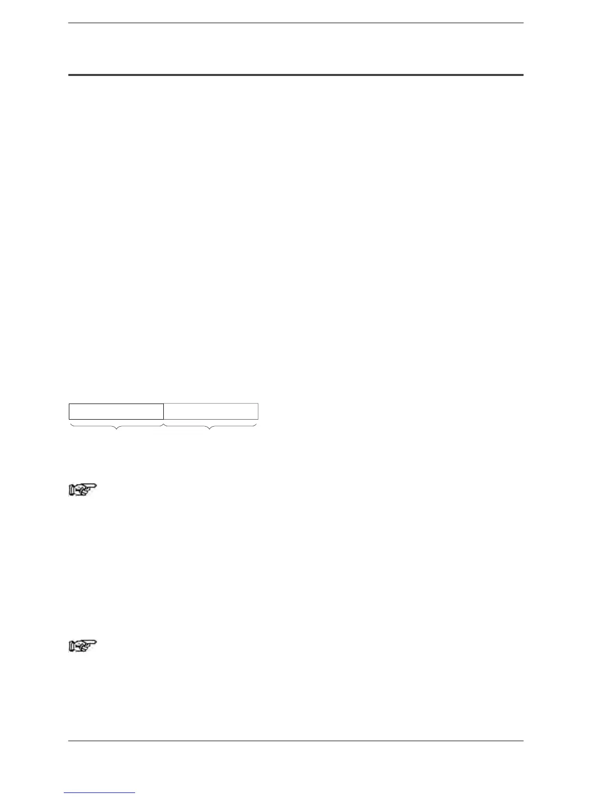
When a 32−bit constant is modified, the specified index register number and the
following index register number are used in combination to handle the data as a 32−bit
data.
Lower 16−bit areaHigher 16−bit area
Contents of InContents of In+1
The results of modification will be 32−bit data.
Note
When 32−bit constants are being modified, ID should not be
specified.
The following index modifications are possible
Memory area numbers used with high-level instructions
K constants (16-bit and 32-bit) and H constants (16-bit and 32-bit) specified with
high-level instructions
Note
There are some cases in which index modification cannot be
specified, depending on the instruction. Confirm the table of
“Operands” on the page describing the various instructions.
 Loading...


