High−level Instructions
3 − 683
Outline Adds two real number data items and stores the result in the specified
area.
For the FP0R/FPΣ/FP−X/FP0/FP−e, the P type high−level instruction
“P310 (PF+)” is not available.
Program example
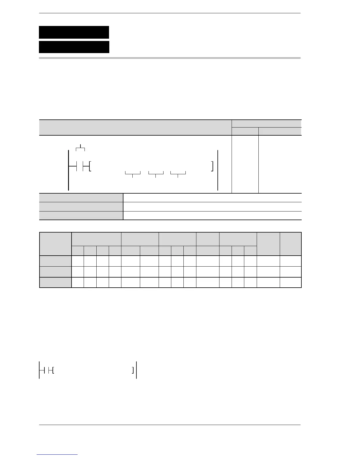
Boolean
Ladder Diagram
Address Instruction
S1
Trigger
S2 D
F310 F+, DT10, DT20, DT3010
R0
10
11
ST R 0
F310 (F+)
DT 10
DT 20
DT 30
S1 Real number data (2 words) or lower 16-bit area of 32-bit data (for augend)
S2 Real number data (2 words) or lower 16-bit area of 32-bit data (for addend)
D Lower 16-bit area of 32-bit data (for result)
Operands
O
WX WY WR WL SV EV DT LD FL I K H f
modifier device
S1 A A A A A A A A A A A A A A* A
S2 A A A A A A A A A A A A A A* A
D N/A A A A A A A A A A N/A N/A N/A A A
* Index modification of a real number is not possible.
Description
The real number data (2 words) specified by S1 and S2 are added together when the trigger turns on. The
added result is stored in D+1 and D.
[S1+1, S1] + [S2+1, S2] → [D+1, D]
Specifying the integer device with [S1] and[S2], the integer data is internally converted to real numbers
before operations continue.
F310 F+, % DT 0, % DT 2, DT 4
R0
F310
P310
(PF+)
(F+)
Floating point data addition





 To Next Page