SWITCH INDICATION
FV-01WS2 Switch (Fig.
28)
"
I "-Power ON
(10
CFM)
"O"
-
Power OFF
FV-04WS2 Switch (Fig.
28)
"
II
"-
Power ON high speed
(40
CFM)
"O"- Power OFF
"
I
"-
Power ON low
speed(20
CFM)
FV-01WS2 FV-04WS2
I
o
Switch
I I
o
I
Fig.
28
PRACTICAL GUIDE TO INSTALLATION
Properly insulate the area around the fan
to
minimize building heat loss and gain. (Fig.
29)
Loose fill or batt insulation can be placed
directly over the duct in the wall.
Interior wall
covering
X
Fan
body
Indoor
Exterior wall
siding
Hood
Outdoor
Fig. 29
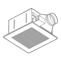
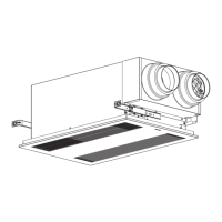
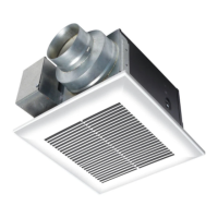
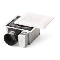
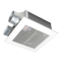
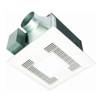
SPECIFICATIONS
Model No.
Duct
diameter
(inches)
Air
direction
Voltage
(V)
Frequency
(Hz)
Noise
(sones)
Power
consumption
(W)
Speed
(r/min)
Air volume
at
0.03"
WG
(CFM)
Weight
Ib.(kg)
FV-01WS2
4 Intake
120
60
<0.3
3.0
2590 10
5.3(2.4)
FV-04WS2 6
Intake
Hi
120
60 1.2 8.5
2520
40
6.8
(3.1)
Lo
120 60
<0.3
5.5
1680
20
HVI Certified performance based on HVI Procedures
915,
916 and 920.
11