INSTALLATION I
-
Wall thickness is
4.5"~
6"
(1
14mm~1 52mm)
6. Open knock-out hole and unscrew the screw
holding the junction box cover. After removing
junction box cover,
secure conduit or
stress
relief on the knock-out hole. (Fig.
6)
7. Refer to wiring diagram (page
5).
Follow all the
local electrical safety codes as well as the National
Electrical
Code
(NEC). Using UL approved wire nuts,
connect house power wires to ventilating fan wires.
Insure the wires are attached so that the wire
connections within the Junction Box can be
re-inserted into the Duct Unit. (Fig.
7)
8. Reattach the junction box cover to junction box by
using screw. (Fig.
8)
A
CAUTION
Mount junction box cover carefully
so
that lead wires are not pinched.
9. Reinstall junction box back into
duct
unit
by
using screws . (Fig.
9)
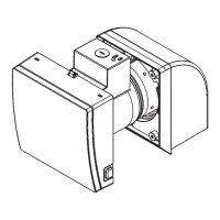
1 0. Detach the panel from fan body by pushing
up
and pulling outward the tab at the base
of the
panel. (Fig.
10)
11. Open the cover in the top right corner of the
fan body to allow the junction box pigtail and
plug to come through. Insert the plastic duct
of the fan body into the metal duct unit and
secure it with 2 screw I
(M4X10) in accessory.
(Fig.
11)
A
CAUTION
Mount fan body carefully so that lead
wires are not pinched.
Flexible Conduit
Junction box
Junction box cover
Fig.
6
Earth ground
to
green
Fig.
7
Screw
Junction box
cover
Junction box
The pin must insert
to the hole
Fig.8
Junction box
Screws
Duct unit
Fig.
9
Fan bod
y
Fig.10
Screwl
Fan body
Duct unit
Fig. 11
7