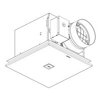
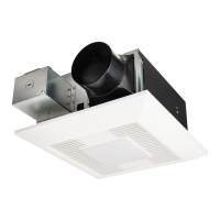
DIMENSIONS
Unit: inches (mm)FV-0511VFL1 and FV-0511VFL1K
10 3/8 (263)
5 1/4 (133)
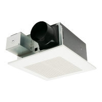
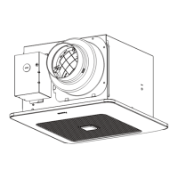
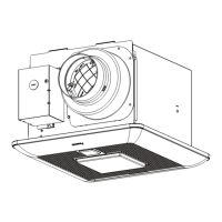
Part name
Grille
Blade
Junction box
Adaptor
PCB box
Pick-A-Flow switch
Part name
No. No.
Fan body
Damper
Flex-Z Fast bracket
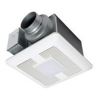
Adjustable color temperature
switch (FV-0511VFL1K only)
5
8
9
10
1
4
2
3
TM
Duct reducer
(optional part)
12
11
FV-0511VFL1 and FV-0511VFL1K
WIRING DIAGRAM
FEATURES
Main control circuit
Fan body
LED
DC
Motor
Junction box
AC 120 V 60 Hz
(Power supply)
AC 120 V 60 Hz
(Power supply)
White
Black
Live
(
Fan
)
Neutral
White
Black
Blue
Green
(Ground wire)
Main
control
circuit
5 5/8 (143)
10 3/4 (271)
2 3/4 (69.7)
2 7/8 (71.4)
1 3/8 (32.6)
1 1/2 (37)
13 (330)
9
10
13 (330)
8
3 7/8 (96.7)
5 5/8 (140)
12 1/8 (307)
1
5
6
3
7
2
Duct length, elbows and other factors increase static pressure which can hinder the performance of
most ventilation fans. These products utilize SmartFlow microchip technology that monitors the static
pressure in the system and speeds up or slows down the rpm of the fan depending upon the amount
of resistance within the ducts. This feature allows the fan to perform as rated and avoid potential
installation issues.
These products are built using DC motor technology. The DC motor is 30 % ~ 70 % more energy
efficient than the minimum ENERGY STAR requirements.
Power switch
Power switch
Power switch
Live (N. Light)*
Neutral
Live (Light)
*Night Light
11
12
5
English
 Loading...