INSTALLATION
I
(JOIST
MOUNTING-
I)
CONTINUED
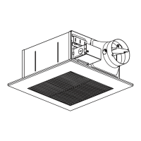
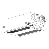
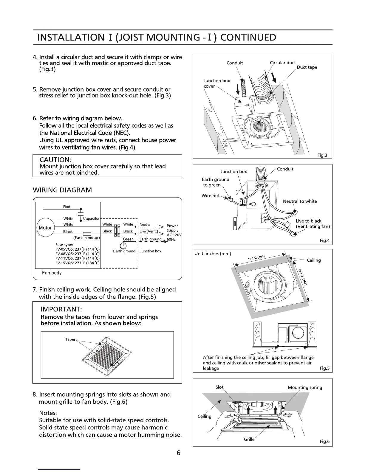
4. Install a circular
duct
and secure
it
with
clamps
or
wire
ties and
seal
it
with
mastic
or
approved
duct
tape.
(Fig.3)
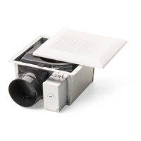
5.
Remove junction box cover and secure conduit
or
stress
rehef
to
junction box knock-out hole. (Fig.3)
6.
Refer
to
wiring diagram below.
Follow all
the
local electrical safety
codes
as
well
as
the
National Electrical Code
(NEC).
Using
UL
approved wire nuts, connect house power
wires
to
ventilating
fan
wires. (Fig.4)
CAUTION:
Mount
junction box cover carefully so
that
lead
wires are
not
pinched.
WIRING DIAGRAM
Red
_L
Whne
Tcapacltor
------------
I
,~\
While
Whlta
"'~
Whne:
:~~-
->
Power
'e)
Black Black
Ul
Black : LI"'!JV:entJ >
Supp~O\
,-
-
AC12
(Fuse
in motor)
u'
Green : Earth i..round
~60Hz
Fuse
type:
@1--
--
I
FV-IlSVQS:
237
'F
(114 '
C)
Earth
-ground
:
Junction
box
FV-IlBVQS:
237
' F (114 '
C)
I
FV-1
1VQS:
237
' F (114 "
C)
I
FV-15VQS:
273
' F (134
"C)
I
I
I
----------
Fan
body
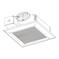
7. Finish ceiling
work.
Ceiling hole should be aligned
with
the
inside edges
of
the
flange. (Fig.S)
IMPORTANT:
Remove
the
tapes
from
louver
and
springs
before installation. As
shown
below:
8. Insert
mounting
springs
into
slots
as
shown
and
mount
grille
to
fan
body. (Fig.6)
Notes:
Suitable
for
use
with
solid-state speed controls.
Solid-state speed controls may cause harmonic
distortion
which can cause a
motor
humming
noise.
6
Conduit
duct
Duct tape
Unit: inches
(mm)
After
finishing
the
ceiling job, fill gap between flange
and ceiling
with
caulk
or
other sealant
to
prevent air
leakage
Fig.5