©PanasonicCorporation2012
For keeping
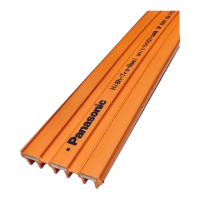
High-Tro-Reel Operation Manual
<Tension Type>( Without CE Type ) Indoor Use Only
■Before using, be sure to read through this Operation / Installation Manual and use the product correctly.
■After reading, keep this Operation / Installation Manual with you for your reference.
■Ask qualified electrician for troubleshooting and maintenance.
Please be sure to show this Operation / Installation Manual to that engineer.
■We have quality, strive to improve reliability, however, It finally becomes difficult the continuing use due to the
deterioration of the material.Deterioration is different in use conditions like the availability and the ambient
environment, etc. butdegrading the year.
In the worst case degradation is the cause of the fire burning. so we recommend early inspection and replacement.
・
For a long time - you use this product on your own, "Maintenance Table" Please always check regularly once a year based on the least.
・If you have trouble checking in, please contact the electrician.
・This product is an important asset - customers. Please check and the following things must be observed.
・This product is an important asset of customers. Please check and understand the following text carefully.
In addition, safety precautions, to the extent expected by the Company are listed.
Installation of the High-Tro-Reel must be performed only by a licensed electrician. To prevent injury or accidents, always pay attention
to the following points.
Precautions on installation
●
Do not modify the Tro-Reel HS in any way. Otherwise, electric shock, fire or damage due to falling of equipment may occur.
●
Do not use where exposure occurs. Otherwise, electric shock, fire or damage due to falling of equipment may occur
●
Use at ambient temperature -10 ℃ ~ 40 ℃. If you use outside this temperature range, please contact Panasonic Corporation.
●
If any abnormalities occur, turn off the power immediately and contact a qualified electrician for inspection and repair.
Otherwise, electric shock, fire or damage due to falling of equipment may occur.
●
The replacement product is required for electrical worker qualifications.
●
Do not use the collector shoes past replacement indication lines.
Otherwise, a unit may produce sparks, causing fire, poor contact or separation of collector arms from wires.
●
To prevent electric shock, be sure to turn off the power before starting any inspection. Otherwise, electric shock may occur.
●
Be sure to do a pre-use test run of equipment and do periodic inspections.
Otherwise, electric shock, fire or damage due to falling of equipment may occur.
●
When damage and crack occurred in the insulating sheath of the duct, please change the duct.
Otherwise sparking may occur, causing fire, poor contact, or derailing of the trolley, etc.
●
This product is for general indoor use only. Do not use this product for a damp place, a place where corrosive gas is
generated or a place where cutting oil is directly splashed. Electric shock, fire or damage due to equipment falling may occur.
●
Collector shoes use a dry lubrication system. Do not apply any other lubricants to the collector shoes or a unit’s
conductor surface.poor contact may occur.
●
Traveling speed must be 300m/min. or less. (60m/min.or less in guide caps mounting section). However, further
restrictions may be necessary depending on the load and voltage types. for details, please contact Panasonic Corporation,
Otherwise, a unit may produce sparks, causing fire, poor contact or separation of collector arms from wires.
●
If products are not used for a long period of time, the unit’s conductor surfaces may become oxidized, resulting in poor contact.
Clean the conductors before resuming operation and be sure to do periodic inspections to prevent fire or electric shock.
●
During the inspection, wear protective gear such as helmets and gloves. Observe may cause injury .
●
When mounting the duct to the hanger, stuff a duct into a hanger not to pinch a hand. Observe may cause injury to your fingers.
●
When remove the duct from the joiners, pull it out while holding the tip of the duct. so that the duct may not jump out from Joyner.
Observe, damage to the ducts, may cause injury.
●
When filing the ends of the duct, use protective gear such as glasses. Otherwise, your finger may be injured.
●
Be sure to remove burrs using file after cutting, drilling. Observe may cause injury to your fingers.
●
When replacing the current collector arm, Be sure that collector arms are mounted parallel to the duct unit with no twisting.
Failure to conform to this table may cause poor collector arm contact or separation from wires.
●
When replacing the collector, be sure to confirm the duct unit phase (R.S.T) before connecting the leads to the load.
Failure to do so may cause fire due to sparks.
Warning
Caution
The product-life is different in use conditions and the service space, however, It is possible to use it for about t 10 years
by regularly maintaining and the regular service in correct construction.
PanasonicCorporationPowerComponentsBusinessUnit
1048,kadoma,kadoma,oosaka,571-8686,japanTelephone:+81-06-6908-1131