
M
Miranda BarnesAug 15, 2025
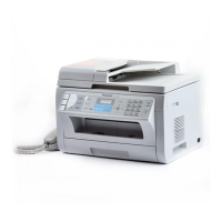
What to do if there is something wrong with the drum cartridge in Panasonic KX-MB2085CXW?
- PPatricia DavisAug 15, 2025
If there's an issue with the drum cartridge in your Panasonic Printer, replace both the drum and toner cartridges.