Do you have a question about the Panasonic KX-TC2100BXB and is the answer not in the manual?
Commercially available PbF solder types and recommended wire sizes.
Identifying PbF markings on PCBs.
Procedures for recharging and replacing the handset battery.
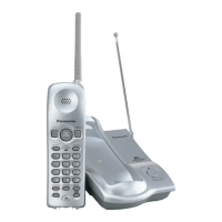
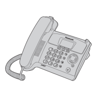
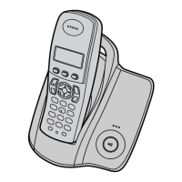
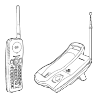
Identification of controls on the base unit and handset.
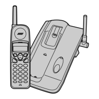
Step-by-step guide for connecting the base unit and handset.
Common problems and their solutions for the unit.
Steps to verify power supply to the base unit and handset.
Procedures to check if the unit receives bell signals correctly.
Steps to verify the battery charging process.
Troubleshooting steps to ensure base unit and handset link.
Guide to check if the handset transmits audio signals properly.
Guide to check if the handset receives audio signals properly.
Flowchart for entering and operating the base unit test mode.
Method for switching between communication channels.
Specific adjustment procedures and parameters for the base unit.
Reference diagram for base unit adjustment points and equipment.
Flowchart for entering and operating the handset test mode.
Method for switching between communication channels.
Specific adjustment procedures and parameters for the handset.
Reference diagram for handset adjustment points and equipment.
RF specifications for the base unit.
RF specifications for the handset.
Communication sequence for switching between standby and talk modes.
Communication sequence for handling incoming calls and ringing.
Communication sequence for channel selection.
Pin assignments for data transmission and reception.
Visual representation of data signal waveforms.
Overview of the ICs and circuits comprising the base unit.
Explanation of the power supply circuit for the base unit and handset.
Explanation of the reset circuit for the CPU.
Operation of the battery charging circuit.
Functionality of the telephone line interface.
Operation of the transmitter and receiver circuits.
Overview of the ICs and circuits comprising the handset.
Explanation of the reset circuit for the handset CPU.
Detailed pinout and function for IC201 (Base Unit CPU).
Detailed pinout and function for IC701 (Handset CPU).
Pin assignments for IC401 (Base Unit) and IC801 (Handset).
Necessary tools and materials for IC replacement.
Steps for safely removing flat package ICs from the PCB.
Steps for installing new flat package ICs onto the PCB.
Procedure for modifying bridged connections on the PCB.
Terminal guide for components on the base unit.
Terminal guide for components on the handset.
Replacement parts specific to the base unit.
Replacement parts specific to the handset.
List of accessories and packing materials.
Schematic diagram for the base unit.
Schematic diagram for the handset.
Component placement on the base unit circuit board.
Solder side view of the base unit circuit board.
Component placement on the handset circuit board.
Solder side view of the handset circuit board.
| Type | Cordless Telephone |
|---|---|
| Standby Time | Up to 7 days |
| Display | LCD |
| Caller ID | Yes |
| Call Waiting | Yes |
| Number of Handsets | 1 |
| Answering Machine | No |
| Color | Black |
| Phonebook Capacity | 50 entries |