Do you have a question about the Panasonic KX-TES824LA and is the answer not in the manual?
Provides information on commercially available lead-free solder types and recommended wire sizes.
Illustrates the 'PbF' marking on PCBs to identify lead-free solder use.
Outlines essential safety measures for servicing the equipment.
Explains the procedure for insulation resistance testing.
Warns about dangers of incorrect battery replacement and disposal.
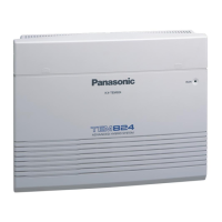
Provides an overview of the system's basic features and capabilities.
Details electrical and performance characteristics like loop limits and voltage.
Lists the maximum number of CO lines and extensions for different system configurations.
Lists the main units and optional service cards used in the system.
Illustrates how various devices connect to the main system unit.
Explains how to connect the unit to a PC via RS-232C or USB.
Provides step-by-step instructions for disassembling the unit.
Presents the overall system architecture and component interconnections.
Illustrates the power distribution and supply within the system.
Shows the block diagram for the 1AP interface.
Details the block diagram for the 2AP interface.
Provides a block diagram of the power supply unit.
Explains the functions of the main unit's circuits.
Describes the circuit linking CO lines to the cross-point section.
Explains the space division switching system for connecting various circuits.
Details the interface circuit for single-line telephones.
Explains the APT i/f module for private machine communication.
Describes the CPU, ROM, SRAM, and ASIC for system control.
Summarizes circuits for USB, OGM, Ring Signal, SMDR, Door Phone, Call ID, and BV.
Explains the functions of the power unit, including AC-DC conversion and battery backup.
Details the composition and operation of the CO interface circuit.
Explains the operation of the cross-point switch ICs.
Details the circuit operation for extension telephones and hook detection.
Summarizes circuits for data communication, tone generation, and DTMF.
Details circuits for USB, OGM, Ring Signal, SMDR, Door Phone, Call ID, and BV.
Provides a flowchart for diagnosing and resolving 'no operation' issues.
Offers troubleshooting steps for missing dial tone on the main board.
Provides guidance for troubleshooting issues related to dialing and calling.
Covers troubleshooting common problems specific to the sub board.
Provides pin configuration and function details for IC700.
Lists pin assignments and functions for IC6, IC7, and IC8.
Details the pin configuration and functions for IC10.
Summarizes IC data for various optional cards.
Shows pin configurations for various integrated circuits.
Illustrates pinouts for common transistors used in the system.
Provides pin configurations for various diodes.
Details necessary preparations and the procedure for removing ICs.
Explains the steps for correctly installing new ICs onto the PCB.
Identifies screw types and their locations for cabinet assembly.
Lists replaceable cabinet and electrical components.
Details included accessories and packing materials.
Lists all replaceable parts for the main board.
Shows the top view of the main board with component placement.
Illustrates the bottom view of the main board showing solder traces.
Illustrates the 'PbF' marking on PCBs to identify lead-free solder use.
Provides instructions for physically installing the 4-Port Doorphone Card.
Presents the card's block diagram and explains its circuit operations.
Offers solutions for common problems and IC pinouts for the doorphone card.
Lists all replaceable parts for the KX-TE82461X card.
Shows how to identify Pb-free solder markings on the PCB.
Details the procedure for installing the 8-Port SLT Extension Card.
Presents the block diagram illustrating the card's architecture.
Explains the operation of the cross-point switch circuits on the card.
Provides guidance for diagnosing and resolving issues with the card.
Lists all replaceable parts for the KX-TE82474X card.
Shows how to identify Pb-free solder on the card's PCB.
Provides instructions for installing the KX-TE82480X card.
Presents the overall block diagram of the KX-TE82480X card.
Explains the operation of the CO interface circuit.
Provides troubleshooting steps for common issues with the card.
Lists all replaceable parts for the KX-TE82480X card.
Shows how to identify Pb-free solder marks on the card's PCB.
Provides instructions for installing the KX-TE82483X card.
Presents the card's block diagram and its functional sections.
Explains the operation of the CO interface circuit.
Offers troubleshooting steps for common issues with the card.
Lists all replaceable parts for the KX-TE82483X card.
Illustrates how to identify Pb-free solder on the card's PCB.
Provides instructions for installing the message extension card.
Presents the card's block diagram and its main components.
Explains the voice record/play circuit operation.
Offers troubleshooting steps for PBX and message recording issues.
Lists all replaceable parts for the KX-TE82491X card.
Shows how to identify Pb-free solder marks on the card's PCB.
Provides instructions for installing the voice message card.
Presents the card's block diagram and its functional components.
Explains the card's voice record/play circuit operation.
Offers troubleshooting steps for PBX and message playback issues.
Lists all replaceable parts for the KX-TE82492X card.
Illustrates how to identify Pb-free solder on the card's PCB.
Provides instructions for installing the 3-Port Caller ID Card.
Presents the card's block diagram and its functional units.
Explains the Call ID detect circuits for FSK and DTMF.
Offers troubleshooting steps for issues related to Call ID reception.
Provides pin configuration and function details for IC8.
Lists all replaceable parts for the KX-TE82493X card.
Details the accessories and packing materials included with the cable.
Lists all replaceable parts for the KX-A227X cable.
| Number of CO Lines | 8 |
|---|---|
| Number of Extensions | 24 |
| Caller ID | Yes |
| Voicemail | Yes |
| DISA (Direct Inward System Access) | Yes |
| Voice Mail Integration | Yes |
| Doorphone Interface | Yes |
| Power Failure Transfer | Yes |
| USB for Programming | Yes |
| Expandable | Yes |
| Conference Calls | Yes |
| Intercom | Yes |
| Music on Hold | Yes |
| Power Supply | AC 100-240V, 50/60Hz |
| Type | Hybrid PBX |