Do you have a question about the Panasonic KX-TG2511FXM and is the answer not in the manual?
Precautions for qualified personnel performing repair services to prevent hazards.
Warning regarding the danger of explosion if batteries are incorrectly replaced or disposed of.
Guidance on using lead-free solder, its properties, and precautions for soldering.
Instructions for safely discarding printed circuit boards and personal data.
A block diagram illustrating the functional components and connections of the base unit.
Detailed explanation of the base unit's circuit operations, including key IC functions.
A block diagram showing the functional components and interconnections within the handset.
Explains the handset's circuit operations, including power supply and battery detection.
Outlines the power supply circuit operation for the charger unit.
Traces signal paths for various functions like DTMF, Caller ID, and SP-Phone.
Provides hints for service technicians, covering battery and PIN code usage.
Instructions for accessing and using the engineering mode for unit setup.
Procedures for copying phonebook data between compatible handsets during repair.
Steps to reset units to factory settings, erasing user data.
A flowchart to guide troubleshooting based on symptoms and potential checks.
Procedures for checking power supply issues in the base unit and handset.
Steps to check battery charging functionality for the base unit, handset, and charger unit.
Procedures for checking the link establishment between units.
Steps to identify defective RF parts by checking functionality.
Steps to check the handset's microphone and CDL TX signal path.
Steps to check the handset speaker and CDL RX signal path.
Procedures to verify bell signal reception and sound output.
Guides to troubleshoot common symptoms for base/charger units based on DECT tester.
Specific checks for voltage supplies, BBIC, and EEPROM on the base unit.
Specific checks for the charger unit's charging circuit and voltage supplies.
Guides to troubleshoot handset symptoms based on DECT tester availability.
Specific checks for handset voltage supplies, BBIC confirmation, and EEPROM.
Addresses speakerphone transmission issues due to line conditions or noise.
Step-by-step instructions for disassembling the product units.
Detailed instructions for replacing the LCD screen on the handset.
Lists the necessary equipment for performing measurements and adjustments.
Explains PC settings and JIG connection for base unit measurements.
Shows base unit PCB views with test points for adjustments.
Shows charger unit PCB views with test points for adjustments.
Explains PC settings and JIG connection for handset measurements.
Shows handset PCB views with test points for adjustments.
Procedures for downloading data after component replacement.
RF specifications for the base unit and handset.
Method to check the resistance of the handset speaker and receiver.
Table listing transmit and receive frequencies for channels.
Steps for replacing flat package ICs on the PCB.
Steps for replacing shield cases on the PCB.
Terminal identification for components on the base unit.
Notes on taking DC voltage measurements for schematic diagrams.
The schematic diagram for the base unit, showing component connections.
The schematic diagram for the handset, showing component connections.
The schematic diagram for the charger unit, showing component connections.
Top view of the base unit main PCB showing component placement.
Top view of the handset PCB showing component placement.
Top view of the charger unit PCB showing component placement.
Exploded view and list of cabinet and electrical parts for the base unit.
Exploded view and list of cabinet and electrical parts for the handset.
Exploded view and list of cabinet and electrical parts for the charger unit.
Lists and illustrates the accessories included with the product.
A comprehensive list of replacement parts for all product components.
List of replacement accessories.
List of replacement screws used in the product.
List of replacement fixtures and tools required for service.
| Type | Cordless Telephone |
|---|---|
| Number of Handsets | 1 |
| Frequency | 1.9 GHz |
| DECT | Yes |
| GAP compatible | Yes |
| Caller ID | Yes |
| Call Waiting | Yes |
| Phonebook Capacity | 50 entries |
| Ringer melodies | 10 |
| Talk Time | Up to 10 hours |
| Standby Time | Up to 120 hours |
| Battery type | Ni-MH |
| Display | LCD |
| Display lines | 1 |
| Backlit Display | Yes |
| Speakerphone | No |
| Intercom | No |
| Answering Machine | No |
| Range | Up to 50 meters indoors |
| Redial memory | 10 numbers |
| Expandable | Up to 6 handsets |
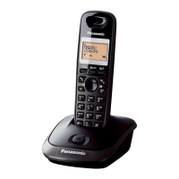
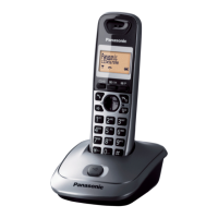
| Color | Black, Silver |