38
KX-TG2521BXT/KX-TGA251BXT
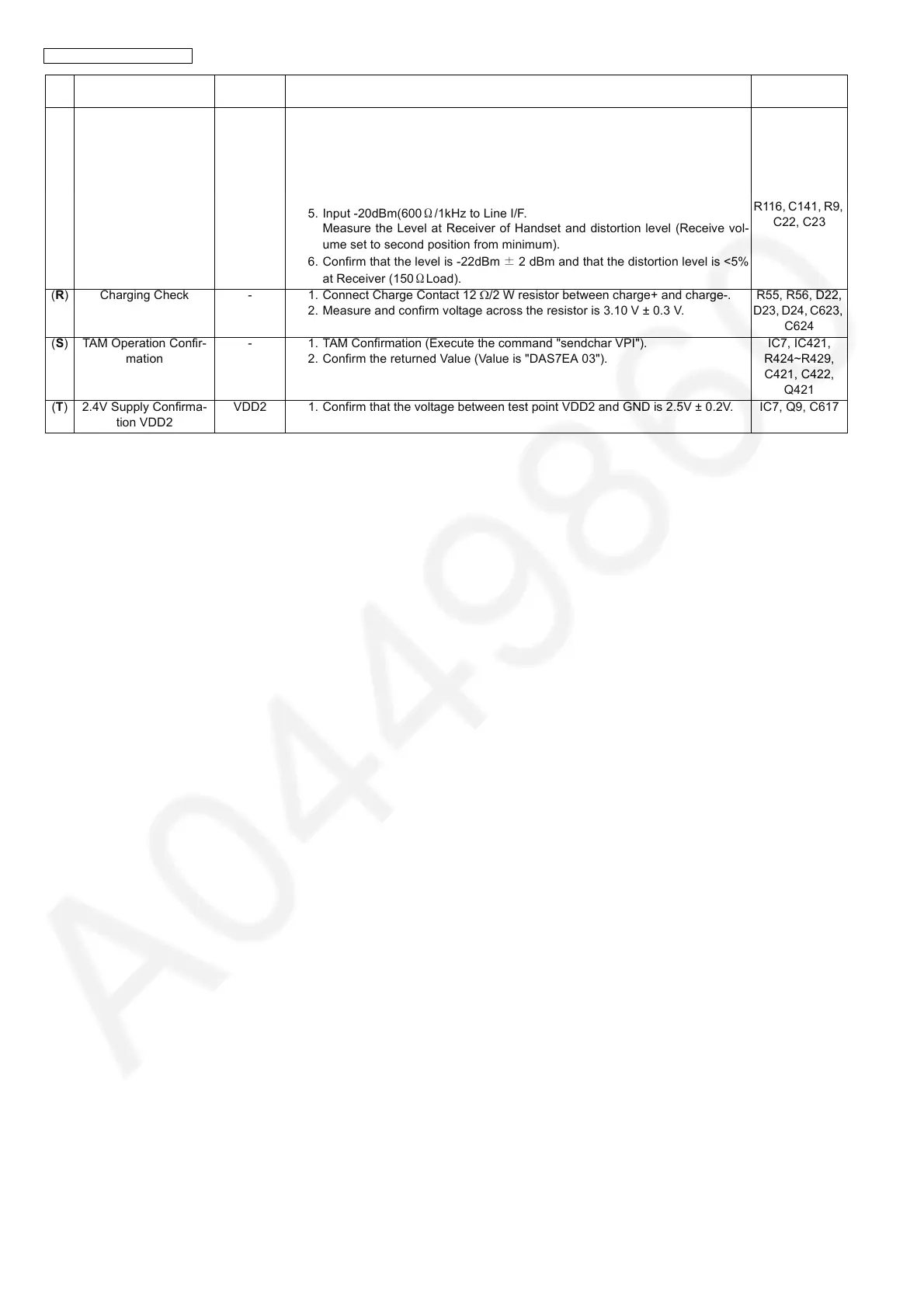
(Q) Audio Check - 1. Link with Handset which is connected to Line Simulator.
2. Set line voltage to 48V and line current to 50mA.
3. Input -45dBm(600Ω)/1kHz to MIC of Handset.
Measure the Level at Line I/F and distortion level.
4. Confirm that the level is -1.5dBm ± 2dBm and that the distortion level is <5%
at TEL Line (600ΩLoad).
5. Input -20dBm(600Ω/1kHz to Line I/F.
Measure the Level at Receiver of Handset and distortion level (Receive vol-
ume set to second position from minimum).
6. Confirm that the level is -22dBm ± 2 dBm and that the distortion level is <5%
at Receiver (150ΩLoad).
IC7, SA1, L1,
L2, D3, Q3, Q4,
R14, R15, R16,
R17, D21, Q5,
R19, R20, C14,
C56, R117,
R116, C141, R9,
C22, C23
(R) Charging Check - 1. Connect Charge Contact 12 Ω/2 W resistor between charge+ and charge-.
2. Measure and confirm voltage across the resistor is 3.10 V ± 0.3 V.
R55, R56, D22,
D23, D24, C623,
C624
(S) TAM Operation Confir-
mation
- 1. TAM Confirmation (Execute the command "sendchar VPI").
2. Confirm the returned Value (Value is "DAS7EA 03").
IC7, IC421,
R424~R429,
C421, C422,
Q421
(T) 2.4V Supply Confirma-
tion VDD2
VDD2 1. Confirm that the voltage between test point VDD2 and GND is 2.5V ± 0.2V. IC7, Q9, C617
Items Check
Point
Procedure Check or
Replace Parts