Do you have a question about the Panasonic KX-TG2360JX and is the answer not in the manual?
Provides precautions for handling ICs and LSIs to prevent static damage during repair.
Warns about explosion danger from incorrect battery replacement and proper disposal.
Provides solutions for common problems related to telephone system operation.
Guides on checking power issues and interpreting error messages.
Procedures for troubleshooting recording and playback malfunctions.
Guides for checking RF components and handset link stability.
Details test modes for TX Burst, RX-CW, and Link confirmation on the base unit.
Outlines test modes for TX Burst, RX-CW, and Link confirmation on the handset.
Guides for checking and adjusting crystal frequency and battery low voltage.
Instructions for resetting user settings to factory defaults.
Lists pin functions and I/O details for the Base Unit's IC501.
Lists pin functions and I/O details for the Handset's IC201.
Details the pinout and functions of the RF Unit's IC901.
Lists necessary tools and materials for replacing flat package ICs.
Step-by-step guide for soldering and replacing flat package ICs.
Terminal diagrams for ICs, transistors, and diodes used in the Base Unit.
Terminal diagrams for ICs, transistors, and diodes used in the Handset.
Lists replacement parts for the Base Unit, including cabinets and PCB components.
Lists replacement parts for the Handset, including cabinets and PCB components.
Illustrates the component layout on the Base Unit's circuit board.
Shows the component layout on the reverse side of the Base Unit's PCB.
Illustrates the component layout on the Handset's circuit board.
Shows the component layout on the reverse side of the Handset's PCB.
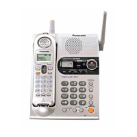
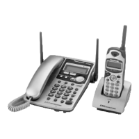
| Number of Handsets | 1 |
|---|---|
| Answering System | Yes |
| Caller ID | Yes |
| Speakerphone | Yes |
| Handset Locator | Yes |
| Call Waiting | Yes |
| Handset Speakerphone | Yes |
| Display | LCD |
| Call Block | No |
| Power Backup | No |
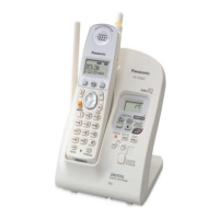
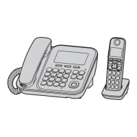
| Type | Cordless Phone |
| Phonebook Capacity | 50 entries |