17.5. Locator/Intercom Mode
1. Press the base LOCATOR/INTERCOM button, then a beep is output from pins 35 and 37 of IC501, and blinks on the SP-
PHONE LED (LED 721) is caused by pin 15 of IC501.
2. At the same time, a beep is output from pin 35, pin 37 of IC501. This status is called “Intercom stand-by“.
3. Then press TALK button of the Handset, the status is changed to "Intercom mode".
4. The receiving signal flows:
RF → pins 35 and 37 of IC501 → SP
The transmission signal flows:
MIC → C447, C448 → RA401 → pins 60 and 61 of IC501 → RF
17.6. Telephone Line Interface
Telephone Line Interface Circuit:
Function
·
Bell signal detection
·
ON/OFF hook and pulse dial circuit
·
Side tone circuit
Bell signal detection and OFF HOOK circuit:
In the idle mode, Q104 is open to cut the DC loop current and decrease the ring load. When ring voltage appears at the Tip (T)
and Ring (R) leads (When the telephone rings), the AC ring voltage is transferred as follows:
T → L101 → R130 → C116 → Q106 → DSP pin 3. [BELL]
When the CPU (DSP) detects a ring signal, Q104 turns on, thus providing an off-hook condition (active DC current flow through
the circuit). Following signal flow is the DC current flow.
T → L101 → D101 → Q104 → Q161 → R164 → D161 → D101 → L102 → P101 → R
ON HOOK Circuit:
Q104 is open, Q104 is connected as to cut the DC loop current and to cut the voice signal. The unit is consequently in an on-
hook condition.
Pulse Dial Circuit:
DSP pin 4 turns Q104 ON/OFF to make the pulse dialing.
Side Tone Circuit:
Basically this circuit prevents the TX signal from feeding back to RX signal.As for this unit, TX signal feed back from Q161 is
canceled by the chancellor circuit of DSP.
76
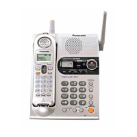
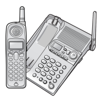
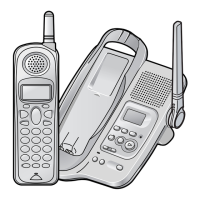
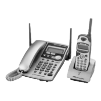
KX-TG2360JXS / KX-TGA236JXS
 Loading...