Do you have a question about the Panasonic KX-TG2360JXS and is the answer not in the manual?
Details recommended lead-free solder types and sizes for service.
Illustrates the "PbF" mark on PCBs to identify lead-free solder usage.
Explains battery charge indicators, strength levels, and recharge procedures.
Provides a step-by-step guide for replacing the handset battery.
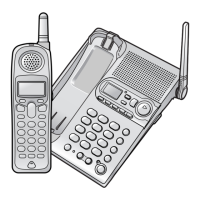
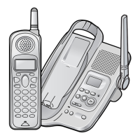
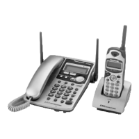
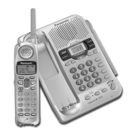
Identifies and labels the controls and indicators on the telephone base unit.
Identifies and labels the controls and displays on the telephone handset.
Explains the various indicators and symbols shown on the base unit's LCD screen.
Lists display messages on the handset LCD and their corresponding causes and remedies.
Details how to connect the base unit to a telephone line and power outlet.
Presents a table outlining the main menu structure and available functions for unit customization.
Provides instructions on how to set the current date and time on the telephone unit.
Lists direct command codes for accessing various functions without navigating menus.
Covers setting up the greeting message, recording, and managing voice messages.
Details the process of saving contact names and phone numbers into the unit's phone book.
Guides on how to activate, deactivate, and use the dial lock feature for security.
Lists common problems related to the telephone system and their solutions.
Addresses issues related to the answering system's recording and playback functions.
Covers general troubleshooting for unit operation, battery status, and time display.
Provides a detailed breakdown of how to disassemble the telephone base unit.
Details the steps required to disassemble the telephone handset.
Guides on troubleshooting power-related issues using a step-by-step diagnostic flow.
Lists error codes displayed on the unit and provides corresponding remedies for each.
Explains how to check the battery charging status and troubleshoot charging problems.
Guides on identifying faulty RF components through a systematic inspection and re-registration process.
Presents a flowchart for testing radio frequency (RF) performance and confirming correct operation.
Provides flowcharts for entering and navigating test modes on the base unit for diagnostics.
Tests and adjusts the frequency of the base unit and handset crystal oscillators.
Shows a diagram of the base unit's PCB with components labeled for identification.
Explains the Frequency Hopping Spread Spectrum technology used for communication.
Illustrates the signal path for both reception and transmission within the telephone system.
Explains the functions of the DSP chip, including voice processing and communication features.
Details the circuit responsible for converting AC power to necessary DC voltages for various blocks.
Explains how the Caller ID information is received and displayed, covering FSK and DTMF formats.
Outlines the step-by-step method for safely removing and installing flat package ICs on a PCB.
Explains techniques for desoldering bridged pins on ICs to ensure proper component replacement.
Provides pinout diagrams and descriptions for ICs, transistors, and diodes on the base unit.
Offers pinout diagrams and descriptions for ICs, transistors, and diodes on the handset.
Lists part numbers and descriptions for electrical components and cabinets for the base unit.
Lists part numbers and descriptions for electrical components and cabinets for the handset.
Shows a visual representation of the base unit's PCB with components identified.
| Brand | Panasonic |
|---|---|
| Model | KX-TG2360JXS |
| Category | Answering Machine |
| Language | English |