9
KX-TG2521BXT/KX-TGA251BXT
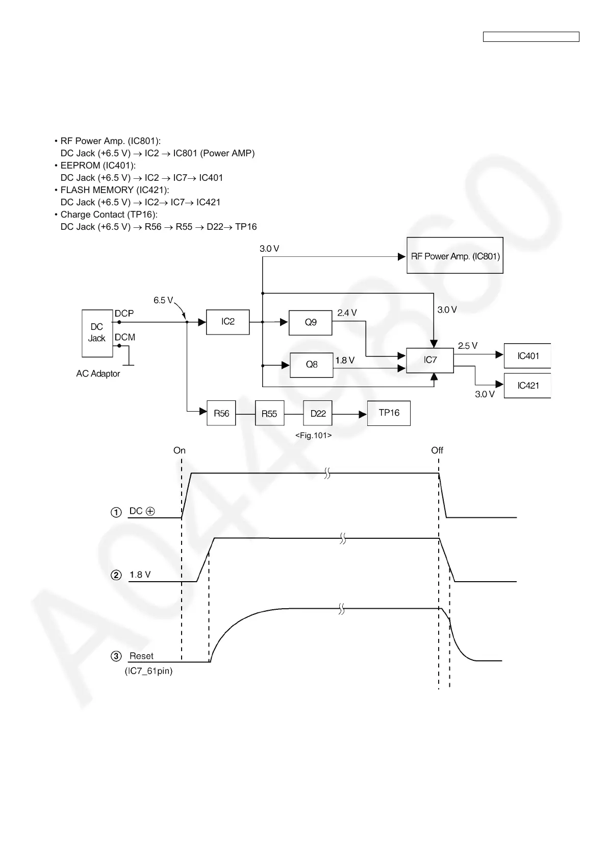
4.2.2. Power Supply Circuit
The power is supplied to the DECT BBIC, RF Module, EEPROM and Charge Contact from AC Adaptor (+6.5 V) as shown in
Fig.101. The power supply is as follows;
• DECT BBIC (IC7):
DC Jack (+6.5 V) → IC2 → IC7
DC Jack (+6.5 V) → IC2 → Q9 → IC7
DC Jack (+6.5 V) → IC2 → Q8 → IC7
• RF Power Amp. (IC801):
DC Jack (+6.5 V) → IC2 → IC801 (Power AMP)
• EEPROM (IC401):
DC Jack (+6.5 V) → IC2 → IC7→ IC401
• FLASH MEMORY (IC421):
DC Jack (+6.5 V) → IC2→ IC7→ IC421
• Charge Contact (TP16):
DC Jack (+6.5 V) → R56 → R55 → D22→ TP16
<Fig.101>




 To Next Page