Do you have a question about the Panasonic KX-TG3531BXS and is the answer not in the manual?
Precautions for technicians to prevent malfunctions due to static electricity.
Danger of explosion if battery is incorrectly replaced.
Information regarding lead-free solder (PbF) used in manufacturing.
Commercially available PbF solder types and recommended wire sizes for service.
Explanation of Frequency Hopping Spread Spectrum technology used in the system.
Details on how the handset and base unit communicate data links.
Visual representation of the main components and connections of the base unit.
Diagram illustrating the radio frequency circuitry of the base unit.
Explanation of how the base unit's circuits function, including DSP and Flash Memory.
Detailed function of the Digital Signal Processor in message handling and communication.
Information about data storage within the Flash Memory IC.
Description of voltage conversion and regulation within the base unit.
Explanation of the circuit responsible for charging the unit.
Function and operation of the circuit used to initialize the microcomputer.
Details on the circuit handling telephone line connections and signals.
Circuit for detecting parallel phone status and disconnecting the line.
Circuit to judge parallel telephone usage by detecting T/R voltage changes.
Function and data format for receiving Caller ID information.
Block diagram illustrating the main components and connections of the handset.
Diagram showing the radio frequency circuitry of the handset.
Explanation of the functional operation of the handset circuits.
Overview of the main circuit components in the handset.
Functionality of the DSP IC in the handset.
Primary function of the RF section in the handset.
Purpose of the EEPROM IC for storing setting data.
How voltage is supplied to various blocks within the handset.
Details on the battery charging mechanism within the handset.
Information on the ringer and speaker functions of the handset.
How voice signals from the microphone are processed and sent.
How received voice signals are output to the speaker or headset.
General explanation of the RF part's transmit and receive functions.
Details of the modulation/demodulation IC in the base unit RF section.
Function of the modulation/demodulation IC in the handset RF section.
Explanation of the charging process for the charger unit.
Traces the path of various signals within the system.
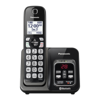
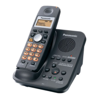
Identifies the location of physical controls on the Base Unit and Handset.
Information on display items and their meanings on the handset.
Steps for connecting the AC adaptor and telephone line to the base unit.
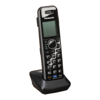
Instructions for connecting the AC adaptor to the handset charger.
Procedure for installing or replacing the handset battery.
Information on charging the handset battery and its performance.
Icons and meanings for indicating battery charge level.
Expected operating times for the handset battery under different usage conditions.
How to customize unit features by programming settings via the handset.
Method for accessing and programming features via the menu structure.
Method for programming features using direct command codes.
How to copy phonebook entries from one handset to another.
Feature to prevent unauthorized calls and its settings.
Common error messages and their corresponding causes and solutions.
Common problems encountered during general use and their solutions.
Flowchart for entering and navigating test modes for the base unit.
Procedure for testing the base unit's burst transmission mode.
Procedure for testing the base unit's continuous wave transmission mode.
Procedure for testing the base unit's continuous wave reception mode.
Procedure for testing the link between base unit and handset.
Steps for adjusting base unit parameters like frequency.
Procedure for testing the handset's burst transmission mode.
Procedure for testing the handset's continuous wave transmission mode.
Procedure for testing the handset's continuous wave reception mode.
Procedure for testing the link between handset and base unit.
Steps for adjusting handset parameters like battery low voltage.
Procedure to reset units to factory settings, erasing user data.
Steps for clearing user settings on the base unit.
Steps for clearing user settings on the handset.
Procedures for copying phonebook data during repair scenarios.
A flowchart to diagnose and resolve common issues.
Diagnostic steps to check power supply issues on the base unit.
Steps to troubleshoot issues with recording greeting or incoming messages.
Diagnostic steps to verify the playback function of recorded messages.
Procedures to check and troubleshoot battery charging problems.
Diagnostic steps to verify the wireless link between base unit and handset.
Procedures to diagnose and identify defective RF components.
Methods to pinpoint faulty components in the RF section.
Steps to register a handset to the base unit.
Procedure to remove a handset registration from the base unit.
Method to unregister all handsets from the base unit simultaneously.
Flowchart for systematically checking RF part functionality.
Table outlining checks for RF components in Base Unit and Handset.
Procedure to test the wireless range and sensitivity of the unit.
Visual representation of signal waveforms at the RF-DSP interface.
Diagnostic steps to verify the handset's signal transmission.
Diagnostic steps to verify the handset's signal reception.
Steps to troubleshoot issues related to Caller ID functionality.
Step-by-step guide for replacing flat package integrated circuits.
Tools and materials needed for IC replacement.
Detailed procedure for safely removing an IC from the PCB.
Step-by-step guide for correctly installing a new IC onto the PCB.
Method for removing unwanted solder bridges after soldering.
Guide for replacing LLP type integrated circuits.
Necessary tools and materials for LLP IC replacement.
Important safety and handling precautions during LLP IC replacement.
Procedure for removing an LLP IC using hot air desoldering.
Steps for installing a new LLP IC onto the PCB.
Method for clearing solder bridges on LLP IC installations.
Step-by-step instructions for disassembling the base unit.
Step-by-step instructions for disassembling the handset.
Step-by-step instructions for disassembling the charger unit.
Procedure for replacing the LCD screen on the handset.
Instructions for correctly soldering the antenna PC board.
Post-replacement steps for ICs or crystals, including frequency checks.
Procedure to check and adjust the base unit's crystal oscillator frequency.
Procedure to check and adjust the handset's crystal oscillator frequency.
Steps to adjust battery low voltage settings after EEPROM replacement.
Diagram showing component layout and test points for the base unit.
Diagram showing component layout and test points for the handset.
Table listing frequency values for different channels.
General notes and safety information regarding schematic diagrams.
Reference to the schematic for the base unit's main circuitry.
Reference to the schematic for the handset's main circuitry.
Reference to the schematic for the charger unit's circuitry.
Detailed schematic of the base unit's main electronic components and connections.
Schematic diagram of the base unit's radio frequency circuit.
Schematic showing the operational logic and control circuits of the base unit.
Detailed schematic of the handset's main electronic components and connections.
Schematic diagram of the handset's radio frequency circuit.
Schematic diagram of the charger unit's electronic components.
Visual layout of components on the Base Unit Main PCB.
View of the Base Unit Main PCB's solder side, showing traces.
Component layout diagram for the Base Unit RF PCB.
Diagram showing the Base Unit Antenna PCB layout.
Component layout diagram for the Base Unit Operation PCB.
View of the Base Unit Operation PCB's solder side.
Visual layout of components on the Handset Main PCB.
View of the Handset Main PCB's solder side.
Component layout diagram for the Handset RF PCB.
Component layout diagram for the Charger Unit PCB.
View of the Charger Unit PCB's solder side.
Pin data and I/O status for the Base Unit's main CPU (IC501).
Pin data and I/O status for the Handset's CPU (IC501).
Explanation of the terminals for the RF IC (IC701).
Terminal pinouts for ICs, transistors, and diodes in the Base Unit.
Terminal pinouts for ICs, transistors, and diodes in the Handset.
Exploded view and parts list for the Base Unit's physical and electrical components.
Exploded view and parts list for the Handset's physical and electrical components.
Exploded view and parts list for the Charger Unit's physical and electrical components.
List and illustration of accessories and packing materials for specific models.
List and illustration of accessories and packing materials for specific models.
List and illustration of accessories and packing materials for specific models.
List of parts for the Base Unit, including cabinet, electrical, and PCB components.
List of cabinet and electrical parts for the base unit.
List of main PCB components for the base unit.
List of components for the base unit's operational PCB.
List of cabinet and electrical parts for the handset.
List of main PCB components for the handset.
List of cabinet and electrical parts for the charger unit.
List of main PCB components for the charger unit.
List of accessories and packing materials for KX-TG3531 models.
List of accessories and packing materials for KX-TG3532 models.
List of accessories and packing materials for KX-TGA351 models.
List of screw types used in the product.
List of necessary fixtures and tools for repair and maintenance.