Do you have a question about the Panasonic KX-TG3611BXB and is the answer not in the manual?
Lists the specific model numbers covered by this service manual.
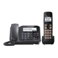
Identifies the device as a 2.4 GHz Digital Cordless Phone.
Specifies the available color options for the product.
Provides safety instructions for service personnel to prevent hazards.
Details important safety measures for battery usage and replacement.
Provides guidance on using and handling lead-free solder.
Instructions for the proper disposal of printed circuit boards.
Explains the Frequency Hopping Spread Spectrum technology used.
Details the operating frequency range and FHSS system.
Describes the TDD frame structure and TDMA system operation.
Illustrates the signal path for device reception and transmission.
Explains the procedure for initiating a communication call.
Details the steps required to terminate a communication.
Describes how the device handles ringing signals.
Shows the main functional blocks of the base unit.
Illustrates the RF components and connections of the base unit.
Details the functions of the DSP and EEPROM in the base unit.
Explains the operation of the base unit's power supply circuit.
Describes the functionality of the base unit's charge circuit.
Explains the operation of the base unit's reset circuit.
Details the circuit handling telephone line connections.
Explains the auto disconnect feature and its circuit.
Describes the circuit for detecting parallel phone line connections.
Explains the processing of Caller ID and Call Waiting ID signals.
Details the CLASS service for receiving caller information during calls.
Shows the main functional blocks of the handset.
Illustrates the RF components and connections of the handset.
Explains the overall operation of the handset's circuits.
Explains the operation of the handset's power supply circuit.
Details the functionality of the handset's charge circuit.
Describes the signal paths for sending and reception.
Explains the overall operation of the RF section.
Describes the power supply voltages for the RF part.
Identifies and describes the physical controls on the device.
Explains the meaning of items displayed on the handset screen.
Provides step-by-step instructions for setting up the device.
Details the process for installing and replacing batteries.
Explains how to configure various device settings.
Instructions for using and managing the dial lock feature.
Lists and explains common error messages and their solutions.
Provides general steps for diagnosing and resolving issues.
Specific steps for troubleshooting Caller ID functionality.
Steps to resolve issues with handset registration.
Steps for troubleshooting problems related to the dial lock.
Important precautions for handling devices with liquid damage.
Provides flowcharts for accessing various test modes.
Steps to enter and perform the Test Burst Mode on the base unit.
Steps to enter and use the TX-CW Mode on the base unit.
Steps to enter and perform the RX-CW Test Mode on the base unit.
Steps to enter and perform the Test Link Mode on the base unit.
Procedure for adjusting the base unit using a PC.
Steps to enter and perform the Test Burst Mode on the handset.
Steps to enter and use the TX-CW Mode on the handset.
Steps to enter and perform the RX-CW Test Mode on the handset.
Steps to enter and perform the Test Link Mode on the handset.
Procedure for adjusting the handset.
Instructions for resetting user settings to factory defaults.
Procedure to reset user settings on the base unit.
Procedure to reset user settings on the handset.
A flowchart to help diagnose and resolve common issues.
Steps to verify the power supply and its components.
Procedures to check the battery's charge status and health.
Steps to verify the communication link between handset and base unit.
Guidance for troubleshooting issues related to the RF section.
Steps to resolve problems with handset registration.
Procedure for removing all registered handsets from the base unit.
Steps for registering a new handset to the base unit.
Steps for deregistering a specific handset.
A flowchart outlining the steps for performing RF checks.
A table detailing checks for various RF components.
Procedures to test and confirm the device's operating range.
Analysis of signal waveforms at the RF-DSP interface.
Analysis of signal waveforms captured during Test Burst Mode.
Steps to verify the handset's transmission capabilities.
Steps to verify the handset's reception capabilities.
Steps to verify the proper functioning of Caller ID.
Lists necessary tools and materials for IC replacement.
Detailed steps for removing a flat package IC from the PCB.
Detailed steps for installing a new flat package IC onto the PCB.
Instructions for removing solder bridges after IC installation.
Lists necessary tools and materials for LLP IC replacement.
Important safety precautions for LLP IC replacement.
Steps for safely removing the component shield case.
Steps for safely installing the component shield case.
Detailed steps for removing an LLP IC using hot air.
Detailed steps for installing an LLP IC.
Instructions for removing solder bridges after LLP IC installation.
General guidance for disassembling the device's components.
Step-by-step instructions for disassembling the base unit.
Step-by-step instructions for disassembling the handset.
Step-by-step instructions for disassembling the charger unit.
Essential steps to perform after replacing integrated circuits.
Procedures to check and adjust the crystal oscillator frequency.
Procedure to adjust the battery low voltage threshold on the handset.
Instructions for building a U-ART interface jig for base unit testing.
Details on connecting the U-ART jig to the base unit and PC.
Pin descriptions and I/O details for the base unit's CPU.
Pin descriptions and I/O details for the handset's CPU.
Details the terminals for the RF integrated circuit.
A general guide to the terminals of various components.
General notes and important safety precautions for schematics.
The primary schematic diagram for the base unit's main board.
Schematic detailing the base unit's power and line interface circuits.
The schematic diagram for the base unit's RF section.
The primary schematic diagram for the handset's main board.
Schematic detailing the handset's power and audio circuits.
The schematic diagram for the handset's RF section.
The schematic diagram for the charger unit.
Shows component placement on the base unit's main PCB.
Shows component placement on the bottom side of the base unit's main PCB.
Shows component placement on the base unit's RF section PCB.
Shows component placement on the handset's main PCB.
Shows component placement on the bottom side of the handset's main PCB.
Shows component placement on the handset's RF section PCB.
Shows component and bottom views of the charger unit PCB.
Exploded view and parts list for base unit cabinet and electrical parts.
Exploded view and parts list for handset cabinet and electrical parts.
Exploded view and parts list for charger unit cabinet and electrical parts.
Lists all accessories included with the product.
Detailed list of replacement parts for the base unit.
Detailed list of replacement parts for the handset.
Detailed list of replacement parts for the charger unit.
List of replacement accessories available for the product.
List of replacement screws and fasteners.
List of replacement tools required for service.
| Brand | Panasonic |
|---|---|
| Model | KX-TG3611BXB |
| Category | Telephone System |
| Language | English |