Do you have a question about the Panasonic KX-TG4771B and is the answer not in the manual?
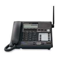
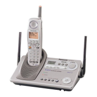
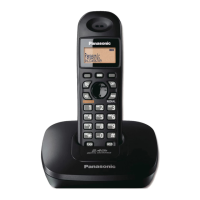
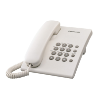
Lists the specific model numbers and system type.
Emphasizes that service is for experienced technicians only.
Highlights critical safety components marked with a symbol.
Provides guidance on using lead-free solder and its properties.
Details essential precautions for repair service.
Outlines steps to prevent static damage to components.
Warns about explosion risk with incorrect battery types and recycling.
Recommends specific lead-free solder types and wire sizes for repair.
Instructs on proper disposal of printed circuit boards, including data deletion.
Details specifications for DECT 6.0, including channels, frequency, and bit rate.
Lists power sources, methods, operations, dimensions, and mass for all units.
Provides step-by-step instructions for entering and using the base unit engineering mode.
Guides users through the portable's engineering mode for data entry.
Instructions for resetting the portable's user settings to factory defaults.
Provides a flowchart to diagnose and resolve common product issues.
Steps to check power supply and reset circuits for the base unit.
Steps to verify power and reset circuits for the portable unit.
Flowchart for troubleshooting problems with message recording on the base unit.
Procedure to modify the auto-disconnect activation time for line conditions.
Instructions for increasing VOX sensitivity to detect smaller voices.
Procedure to determine if the base unit or portable RF part is defective.
A flowchart guiding through link, control signal, frequency, and TX confirmations.
Provides standards for link, frequency, TX confirmation, and range checks.
Step-by-step guide for disassembling the base unit.
Detailed instructions for taking apart the portable unit.
Guide on how to disassemble the charger unit.
Lists necessary tools like DMM, oscilloscope, and frequency counter.
Explains how to connect the JIG and set up the PC for measurements.
Illustrates the base unit's bottom view with test points for adjustments.
Shows the charger unit's bottom view indicating connection points for testing.
Displays the portable unit's component layout with test points for adjustments.
Instructions for downloading data after replacing EEPROM or X'tal on the base unit.
Steps for downloading data after replacing EEPROM or X'tal on the portable unit.
Provides the main schematic diagram for the base unit.
Presents the schematic diagram for the portable unit.
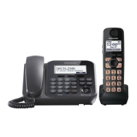
| Color | black |
|---|---|
| Speakerphone | yes |
| Expandable | yes |
| Volume Control | yes |
| Intercom | yes |
| Incoming Lines | 1 |
| New Message Indicator | yes |
| Caller ID | yes |
| Call Waiting | yes |
| Answering System | yes |
| Flash Function | yes |
| Hold Button | yes |
| Caller ID Memory | 99 gigabytes |
| Maximum Incoming Message Length | 18 minutes |
| Handsets | yes |
| Expansion Base Stations | 1, 6 |
| Expansion Handsets | 1, 6 |
| Backlit Keypad | yes |
| Keypad Location | base and handset |
| Bluetooth | no |
| Remote Access | yes |
| Depth | 9 inches |
|---|---|
| Height | 8 inches |
| Net Weight | 64 ounces |