Do you have a question about the Panasonic KX-TG9581B and is the answer not in the manual?
Precautions and guidelines for qualified technicians performing repair services on the product.
Warnings regarding the risk of explosion if batteries are replaced incorrectly and disposal instructions.
Information on lead-free solder (PbF), its properties, and recommended usage for service.
Instructions for safe disposal of printed circuit boards, emphasizing data deletion.
Illustrates the functional blocks and interconnections of the base unit's main circuit.
Explains the functions of key ICs and circuits within the base unit, including audio and RF sections.
Details the base unit's power supply circuits, voltage regulation, and battery backup.
Describes the interface for connecting to the telephone line, including hook detection and ring signals.
Covers audio circuits, DTMF tones, and signal paths for transmitting and receiving voice and data.
Explains the functions of key ICs and circuits within the handset, including power and charge.
Explains how the handset detects low battery status and initiates power down.
Describes the function of the hands-free loudspeaker for ring alarms.
Details the process of pairing a handset with the base unit for system operation.
Explains how to remove a handset's registration from the base unit, freeing it from the system.
Instructions for accessing and using the engineering mode for testing base unit functions.
Details the engineering mode procedures specific to the handset for testing its functions.
Procedures to reset the unit to factory settings, clearing user data and configurations.
A visual guide to diagnose and resolve common issues by following a logical decision tree.
Step-by-step diagnosis for power-related problems in the base unit, starting with adapter and battery checks.
Procedures to verify and troubleshoot the wireless link between the base unit and the portable handset.
Methods for diagnosing RF issues by checking signal confirmation and frequency.
Troubleshooting steps for handset functions including transmission, reception, caller ID, bell, TAM, USB, and Bluetooth.
Lists specific check points and procedures for diagnosing base unit issues based on observed symptoms.
Lists specific check points and procedures for diagnosing handset issues based on observed symptoms.
Step-by-step guide on how to disassemble the base unit for component access and repair.
Detailed instructions for disassembling the handset unit to access internal components.
Step-by-step guide for replacing the LCD module on the base unit.
Detailed instructions for replacing the LCD screen on the handset unit.
Lists necessary tools and equipment for performing measurements and adjustments.
Explains JIG connection and PC setup for base unit measurements and adjustments.
Details installing batch files and lists commands for base unit testing.
Explains JIG connection and PC setup for handset measurements and adjustments.
Details installing batch files and lists commands for handset testing.
Instructions for downloading data after replacing ICs or crystals on the base unit and handset.
Lists DECT and Bluetooth channel frequencies for reference during testing.
Guide to remove and replace flat package ICs using basic tools and solder.
Instructions for safely removing and replacing Leadless Leadframe Package (LLP) ICs.
Provides terminal pinouts and identification for components on the base unit.
Provides terminal pinouts and identification for components on the handset.
Detailed circuit diagrams for the base unit's main, operation, LCD, and LED sections.
Comprehensive circuit diagram for the handset, covering RF, power, and interface sections.
Top-side view of the base unit's main PCB, showing component placement.
Bottom-side view of the base unit's main PCB, showing solder side and connector locations.
Top-side view of the base unit's operation PCB, showing component placement.
Bottom-side view of the base unit's operation PCB, showing component placement.
Component layout on the base unit's LCD circuit board.
Component layout on the base unit's TEL Jack circuit board.
Bottom view of the base unit's TEL Jack circuit board.
Top-side view of the handset's main PCB, showing component placement.
Bottom-side view of the handset's main PCB, showing component placement.
Exploded diagram and list of cabinet and electrical components for the base unit.
Exploded diagram and list of cabinet and electrical components for the handset.
Exploded diagram and list of cabinet and electrical components for the charger unit.
Lists accessories and packing materials included with the KX-TG9581B, KX-TG9582B, and KX-TGA950B models.
Lists replacement parts for the base unit's cabinet and electrical components.
Lists replacement parts for the base unit's main printed circuit board.
Lists replacement parts for the base unit's operational printed circuit board.
Lists replacement parts for the base unit's TEL Jack printed circuit board.
Lists replacement parts for the base unit's LCD printed circuit board.
Lists replacement parts for the base unit's LED printed circuit board.
Lists replacement parts for the handset's cabinet and electrical components.
Lists replacement parts for the handset's main printed circuit board.
Lists various types of screws used in the device for assembly and disassembly.
Lists required fixtures and specialized tools for repair and maintenance procedures.
| Elderly phone | - |
|---|---|
| Mounting type | Desk/Wall |
| Product color | Black |
| AC input frequency | 1.9 Hz |
| Noise reduction | Yes |
| Phonebook capacity | 3000 entries |
| Languages support | ENG, ESP |
| Type | DECT telephone |
| Handset type | Wireless handset |
| Number of ringer volume levels | 7 |
| Redial list capacity | 10 |
| Backlight color | White |
| Display diagonal | 3.4 \ |
| Display resolution | 103 x 65 pixels |
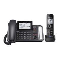
| Number of handsets included | 1 |
| Base weight | 856 g |
|---|---|
| Handset weight | 133 g |
| Base dimensions | 175 x 122 x 259 mm |
| Handset dimensions (WxDxH) | 31 x 168 x 48 mm |