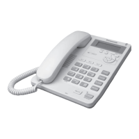
Ref. No. Part No. Part Name & Description Remarks
A1 KX-TCA1-G AC ADAPTOR
A2 PQJA10075Z CORD, TELEPHONE
A3 PQJA10088Z CORD, TELEPHONE
A4 PQJA212V CORD, CURL
A5 PQJXC0401Z HANDSET
A6 PQQX13437X INSTRUCTION BOOK
A7 PQQW12702Z QUICK GUIDE (for English)
A8 PQQW12703Z QUICK GUIDE (for Spanish)
A9 PQQW12576Z LEAFLET, #800
A10 PQXDDS400-8 LABEL, SECURITY TAG
A11 PQPD10553Y CUSHION
P1 PQPH89Y PROTECTION COVER
P2 PQPK14042Z GIFT BOX
20. FOR SCHEMATIC DIAGRAM (SCHEMATIC
DIAGRAM)
1. DC voltage measurements are taken with electronic voltmeter
from negative terminal.
(Add 40 mA to telephone line from the loop simulator.)
2. This schematic diagram may be modified at any time with the
development of new technology.
Important Safety Notice: / Components identified by mark have special
characteristics important for safety. When replacing any of these
components, use only the manufacturer´s specified parts.
21. SCHEMATIC DIAGRAM
21.1. Main
21.2. Operation
22. CIRCUIT BOARD
22.1. Main
22.1.1. Component View
22.1.2. Flow Solder Side View
22.2. Operation
22.2.1. Component View
22.2.2. Flow Solder Side View
74

 Loading...
