I/O CIRCUIT AND WIRING DIAGRAMS
I/O circuit diagram Wiring diagram
Users’ circuitInternal circuit
D
Color code of cable type/quick-connection cable
(Brown) +V (Note 1)
(Black) Output 1
100 mA / 50 mA max.
(Note 3,4)
100 mA / 50 mA max.
(Note 3,4)
(White) Output 2
ZD1
ZD2
(Blue) 0 V (Note 1)
Tr1
Tr2
(Pink) External input (Note 2)
* 1
+5V
Load
Load
3
4
1
2
Terminal No. of connector type
Sensor circuit
12 to 24V DC
±10 %
+
–
12 to 24V DC
±10 %
Brown (Note 1)
Black
White
Blue (Note 1)
Color code of cable type/quick-connection cable
Pink (Note 2)
Load
Load
* 1
+
–
Notes: 1) The quick-connection sub cable does not have brown lead wire
and blue lead wire.
The power is supplied from the connector of the main cable.
2) The quick-connection cable does not have a pink lead wire.
Notes: 1)
The quick-connection sub cable does not have +V (brown) and 0 V (blue).
The power is supplied from the connector of the main cable.
2) Connector type LS-401/403 does not incorporate the external
input.
3) LS-401(-C2) is 100 mA max, however, LS-401(-C2) is 50 mA max.
if 5 to 8 ampliers are connected in cascade, and 25 mA max. if 9
to 16 ampliers are connected in cascade.
4) LS-403 is 50 mA max, however, it is 25 mA max. if 5 to 16
ampliers are connected in cascade.
Terminal layout of connector type
+V
Terminal No.
Output 1
Output 2
4
1
2
3
3
4
1
2
* Connector for amplier (CN-EP1) pin position
Terminal No. Connection cable
1
Conductor core wire: Brown
Cable color: Gray
2
Shield wire
3
Conductor core wire: Yellow
Cable color: Black
4
Shield wire
Wiring diagram
White
Blue (Note 1)
Pink (Note 2)
Black
Brown (Note 1)
Color code of cable type/quick-connection cable
* 1
12 to 24V DC
±10 %
Load
Load
+
–
Notes: 1) The quick-connection sub cable does not have brown lead wire
and blue lead wire.
The power is supplied from the connector of the main cable.
2) The quick-connection cable does not have a pink lead wire.
Terminal layout of connector type
+V
Terminal No.
Output 1
Output 2
4
1
2
3
* Connector for amplier (CN-EP1) pin position
3
4
1
2
LS-401(-C2) LS-403
NPN output type
I/O circuit diagram
Users’ circuit Internal circuit
ZD1
ZD2
(Pink) External input (Note 2)
D
T
r1
Tr2
100 mA max. (Note 3)
100 mA max. (Note 3)
(Black) Output 1
(Blue) 0 V (Note 1)
(White) Output 2
0V
2
4
1
3
Color code of cable type/quick-connection cable
Terminal No. of connector type
(Brown) +V (Note 1)
Sensor circuit
* 1
Load
Load
±10 %
+
–
Notes: 1)
The quick-connection sub cable does not have +V (brown) and 0 V (blue).
The power is supplied from the connector of the main cable.
2) Connector type LS-401P does not incorporate the external input.
3) LS-401P is 50 mA max. if 5 to 8 ampliers are connected in
cascade, and 25 mA max. if 9 to 16 ampliers are connected in
cascade.
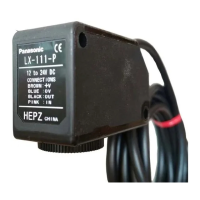
LS-401P(-C2)
PNP output type
* 1
Non-voltage contact or NPN open-collector transistor
or
• External input
High: +5 V to +V, or open
Low: 0 to +2 V (source current: 0.5 mA or less)
• Beam emission halts and teaching occurs
when at Low.
Symbols … D: Reverse supply polarity protection diode
Z
D1
, Z
D2
: Surge absorption zener diode
T
r
1
, T
r
2
: NPN output transistor
* 1
Non-voltage contact or PNP open-collector transistor
or
• External input
High: +4 V to +V (sink current: 3 mA or less)
Low: 0 to +0.6 V, or open
• Beam emission halts and teaching occurs
when at High.
Symbols … D: Reverse supply polarity protection diode
Z
D1
, Z
D2
: Surge absorption zener diode
T
r
1
, T
r
2
: PNP output transistor
Terminal No. Connection cable
1
Conductor core wire: Brown
Cable color: Gray
2
Shield wire
3
Conductor core wire: Yellow
Cable color: Black
4
Shield wire
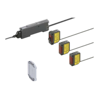
Digital Laser Sensor LS-400 SERIES
11
 Loading...