DIMENSIONS (Unit: mm in)
The CAD data can be downloaded from our website.
25.5
1.004
10
0.394
2-ø6.6 ø0.260 mounting holes
45
1.772
32
1.260
Base
(PA)
8
0.315
18
0.709
20
0.787
28
1.102
20
0.787
1 0.039
20
0.787
1
0.039
25
0.984
33
1.299
0.701
12
0.472
11.8
0.465
44.5
1.752
218
8.583
147
5.787
28
1.102
45°
45°
t 2
t 0.079
6 0.236
20 0.787
Attachment
(Nylon 6)
M4 hexagon-
socket-head
bolt
2-ø3.4 ø0.134
mounting holes
2-3.2 0.126×4.2 0.165
elongated holes
ø10 ø0.394 pipe
[Stainless steel (SUS304)]
Sensor mounting bracket
[Stainless steel (SUS304)]
Cable guide
(POM)
4.2 0.165
3.2
0.126
(Note)
4
0.157
20
0.787
( )
( )
Two M3 (length 14 mm 0.551 in) screws
with washers, two M3 (length 16 mm
0.630 in) screws with washers, two M3
(length 18 mm 0.709 in) screws with
washers, one auxiliary mounting plate for
EQ-20 series and one auxiliary mounting
plate for
series are attached.
11.8
0.465
20 0.787
17.8
0.701
12
0.472
t 2
t 0.079
2-ø3.4 ø0.134
mounting holes
2-3.2 0.126×4.2 0.165
elongated holes
45°
45°
4.2 0.165
3.2
0.126
M4 hexagon-
socket-head
bolt
1 0.039
1
0.039
20
0.787
25
0.984
33
1.299
20
0.787
Attachment
(Nylon 6)
Sensor mounting bracket
[Stainless steel (SUS304)]
ø10 ø0.394 pipe
[Stainless steel (SUS304)]
2-ø6.6 ø0.260
mounting holes
Base
(PA)
32
1.260
46
1.811
20
0.787
8
0.315
15
0.591
31
1.220
20
0.787
36.5
1.437
( )
( )
( )
147
5.787
(Note)
Cable guide
(POM)
10
0.394
24.5
0.965
20
0.787
210
8.268
28
1.102
6 0.236
4
0.157
Two M3 (length 14 mm 0.551 in) screws
with washers, two M3 (length 16 mm
0.630 in) screws with washers, two M3
(length 18 mm 0.709 in) screws with
washers, one auxiliary mounting plate for
EQ-20 series and one auxiliary mounting
plate for EX-40 series are attached.
Note: The dimensions in the brackets indicate the adjustable range of the
movable part.
Note: The dimensions in the brackets indicate the adjustable range of the
movable part.
MS-AJ1
Universal sensor mounting stand (Optional)
MS-AJ2
Universal sensor mounting stand (Optional)
( )
( )
( )
( )
( )
( )
25.5
1.004
10
0.394
2-ø6.6
ø
0.260 mounting holes
45
1.772
32
1.260
Base
(PA)
8
0.315
18
0.709
20
0.787
28
1.102
1.120
12
0.472
0.650
147
5.787
(Note 1)
44.5
1.752
203.5
8.012
134
5.276 (Note 1)
33
1.299
8.268
16.5
0.650
33
1.299
6 0.236
218
8.583
2-ø3.4 ø0.134
mounting holes
Arm joint
(Nylon 6)
ø10 ø0.394 pipe
[Stainless steel (SUS304)]
ø10 ø0.394 pipe
[Stainless steel (SUS304)]
2-3.2 0.126×4.2 0.165
elongated holes
Cable guide
(POM)
Sensor mounting bracket
[Stainless steel (SUS304)]
(Note 2)
4.2
0.165
Two M3 (length 14 mm 0.551 in) screws
with washers, two M3 (length 16 mm
0.630 in) screws with washers, two M3
(length 18 mm 0.709 in) screws with
washers, one auxiliary mounting plate for
EQ-20
series and one auxiliary mounting
plate for EX-40 series are attached.
( )
( )
( )
( )
( )
( )
24.5
0.965
32
1.260
46
1.811
Base
(PA)
31
1.220
15
0.591
8
0.315
10
0.394
20
0.787
2-ø6.6 ø0.260
mounting holes
1.120
12
0.472
0.650
147
5.787
(Note 1)
36.5
1.437
208.5
8.209
134
5.276 (Note 1)
33
1.299
8.268
16.5
0.650
33
1.299
6 0.236
210
8.268
20
0.787
2-ø3.4 ø0.134
mounting holes
Arm joint
(Nylon 6)
ø10
ø
0.394 pipe
[Stainless steel (SUS304)]
ø10
ø
0.394 pipe
2-3.2 0.126×4.2 0.165
elongated holes
Cable guide
(POM)
Sensor mounting bracket
[Stainless steel (SUS304)]
(Note 2)
4.2
0.165
[Stainless steel (SUS304)]
Two M3 (length 14 mm 0.551 in) screws with
washers, two M3 (length 16 mm 0.630 in) screws
with washers, two M3 (length 18 mm 0.709 in)
screws with washers, one auxiliary mounting
plate for EQ-20
series and one auxiliary mounting
plate for
series are attached.
MS-AJ1-A
Universal sensor mounting stand (Optional)
MS-AJ2-A
Universal sensor mounting stand (Optional)
Notes: 1) The dimensions in the brackets indicate the adjustable range of the
movable part.
2) Refer to MS-AJ1 / MS-AJ2 for the assembly dimensions with the
sensor mounting bracket, sensor or reector.
Notes: 1) The dimensions in the brackets indicate the adjustable range of the
movable part.
2) Refer to MS-AJ1 / MS-AJ2 for the assembly dimensions with the
sensor mounting bracket, sensor or reector.
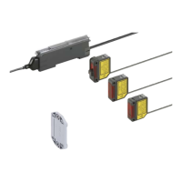
Digital Laser Sensor LS-400 SERIES
17
 Loading...