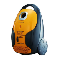
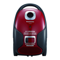
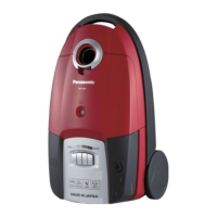
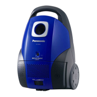
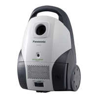
This document outlines the service and maintenance procedures for a Panasonic vacuum cleaner, specifically models MC-CJ913-Y747, MC-CJ913-Y149, MC-CJ913-Y147, MC-CJ913-K747, MC-CJ913-K149, and MC-CJ913-K147. The "Y" in the model number denotes a yellow product color, while "K" indicates black. These models are intended for various destinations, with specific models designated for Saudi Arabia, Kuwait, Iran, and UAE.
The vacuum cleaner is designed for general household cleaning, offering both suction and blower functions. Its primary function is to remove dust and debris from various surfaces using a combination of nozzles and attachments. The suction power can be adjusted to suit different cleaning needs, from delicate surfaces to heavily soiled areas. The blower function provides an alternative method for cleaning in hard-to-reach areas where the nozzle cannot fit.
Usage Features
The vacuum cleaner requires initial assembly before use. This involves connecting the hose, telescopic wand, and floor nozzle securely. The hose unit is inserted into the upper end of the telescopic wand or extension wand, and the floor nozzle is attached to the other end.
To start operation, the user presses the pedal marked with a specific symbol, avoiding the edge of the pedal. The cleaning power can be adjusted by sliding a variable power control, allowing for an increase or decrease in suction as needed.
The vacuum cleaner comes with several attachments to enhance its versatility. The telescopic wand's length can be adjusted to suit the user's height and reach. The floor nozzle is a durable 2-step nozzle designed for different floor types. It can be adjusted to suit either parquet/bare floor surfaces or carpets.
Alternative nozzles are provided for specialized cleaning tasks. A crevice nozzle is included for cleaning narrow gaps, while a dusting brush is suitable for furniture, Venetian blinds, and other delicate surfaces.
A suction regulator is available for situations where strong suction causes the nozzle to stick to the floor, hindering movement. This feature helps to maintain ease of use on various surfaces.
The vacuum cleaner also features a cord rewind pedal. Pressing this pedal, again avoiding the edge, retracts the power cord for convenient storage.
A dust indicator is integrated into the design to alert the user when the cloth dust bag is full. To check the dust indicator, the user should turn the power control to the highest setting and lift the nozzle off the floor. If the indicator turns red, the dust bag is full and needs to be replaced or emptied.
For the blower function, the user must first turn off the appliance and release the connection pipe from the hose inlet. The hose is then connected to the blower inlet. After turning on the appliance, the user can blow out dust. Once finished, the appliance should be turned off, the connection pipe reconnected to the hose inlet, and the appliance can then be used for normal vacuuming to clean any remaining dust.
Maintenance Features
Maintenance procedures are crucial for ensuring the longevity and safe operation of the vacuum cleaner. Before any maintenance or repair, it is imperative to turn off the appliance and remove the power cord and plug from the mains.
The service manual emphasizes several critical points for technicians. When disassembling the vacuum cleaner, technicians must carefully check all connections and wiring, ensuring they are restored correctly upon reassembly. All disassembled components and packaging should be handled with care to prevent accidental damage. After repairs, the area around the repairs must be inspected for any degradation, and all replaced components must be in the correct wiring configurations. A safety test, including insulation resistance and dielectric strength, is required to ensure the vacuum cleaner is safe for subsequent use. Insulation resistance should be at least 5MΩ when 500V DC is applied between the power plug terminals and the exterior of the motor. Dielectric strength requires the appliance to withstand 1250V AC applied between the power plug terminals and the exterior of the motor for one minute.
Technicians are advised not to make changes to models, components, or materials during repairs and services. If a wiring unit is supplied as a spare part, it must be replaced as is, without any additional repairs or connections. Fast-on terminals should be inserted or removed by pushing or pulling them straight out, avoiding jiggling or unnecessary force.
Troubleshooting guidance is provided for common issues. If the motor does not rotate, checks include the continuity of the cord reel unit and rail base unit, as well as the motor itself. For continuity issues, replacement of the cord reel unit or rail base unit may be necessary. If the motor has problems, such as being locked or showing signs of burns, the fan motor unit should be replaced, and the fuse checked.
Fuse blowing can be caused by overcurrent, motor burns, or short-circuiting due to incorrect wiring. If the fuse blows, the underlying cause must be addressed before replacing the fuse. If a motor burn caused the fuse to blow, the motor should also be replaced.
For issues with the P.C.B. Assy (Printed Circuit Board Assembly), internal components should be checked for damage like burns, melting, or breaks in the foil or lead wires. If problems are found, the P.C.B. Assy should be replaced. The TRIAC on the P.C.B. Assy should also be checked for short-circuiting.
If the power control does not function, the ON/OFF switch and the power control volume on the P.C.B. Assy should be checked for continuity and resistance, respectively. Replacement of the P.C.B. Assy may be required if these components are faulty.
Problems with the cord reel, such as the cord not pulling out or not rewinding/locking, require checking the brake lever, the number of spare turns, the cord reel spring, and the correct operation of the brake lever unit. In cases of abnormal cord conditions, the body may need to be separated, the cord untwisted, and then rewound, or the cord reel unit and motor case unit may need replacement.
Low suction power or the motor stopping during vacuuming (due to the thermo protector activating) indicates clogging. The dust bag, filter (in the dust box), hose C unit, and extension wand unit should be checked and cleaned. Any broken dust bag, filter, or hose C unit should be replaced.
Disassembly instructions are detailed for various components, including the dust cover assy, dust bag holder, body cover assy, switch pedal, cord rewind button, upper body, handle cover, guide lever, motor case set, cord reel unit, rail base unit, fan motor unit, P.C.B. assy, and blower cover. Specific cautions are provided, such as the presence of springs during dust bag holder disassembly and the need to be careful not to lose them. Instructions for pretensioning the cord reel unit during assembly are also included, with the number of turns for pretension engraved on the steel plate.
Wiring connection diagrams are provided to ensure correct reassembly of electrical components. The diagrams illustrate the connections between the cord reel unit, rail base unit, ON/OFF switch, P.C.B. assy, ferrite core, lead wire C unit, power control volume, fuse, and fan motor unit, with color-coded wires for clarity.
Exploded views and replacement parts lists are included for both attachments and the main body unit, providing detailed diagrams and part numbers for all components, which is essential for ordering and replacing parts accurately.