EasyManua.ls Logo

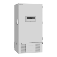
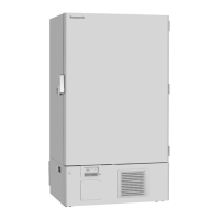
Panasonic MDF-U700VX-PK User Manual

Panasonic MDF-U700VX-PK
57 pages
To Next Page IconTo Next Page
Page #1 background imageLoading...
Page #1 background image
Please read these instructions carefully before using this product, and save this operating instructions
for future use.
See page 54 for all Model Numbers.
MDF-U700VX
MDF-U700VXC
Series
MDF-U700VX
MDF-U700VXC
Ultra-Low Temperature Freezer
Operatin
g
Instructions

Table of Contents

Questions and Answers:

Panasonic MDF-U700VX-PK Specifications

General IconGeneral
BrandPanasonic
ModelMDF-U700VX-PK
CategoryFreezer
TypeUpright Freezer
Temperature Range-50°C to -86°C
Power Supply220-240V, 50/60 Hz
Door LockYes
ColorWhite

Summary

Introduction

Safe Operation Precautions

General Safety Symbols

Defines WARNING, CAUTION, prohibition, and instruction symbols for safe operation.

CO2 Gas Safety

Warns about oxygen depletion with CO2 gas and emphasizes ventilation needs.

Outdoor Use Warning

Do not use outdoors to prevent leakage or electric shock.

Installation Safety

Covers qualified personnel, sturdy floor, and avoiding humid/flammable locations.

Grounding Requirements

Always ground the unit to prevent electric shock.

Power Source Connection

Connect to the specified power source voltage and frequency.

Flammable Substance Storage

Do not store flammable substances if cylinders are unsealed.

Object Insertion Warning

Do not insert metal objects into vents or outlets.

Hazardous Article Handling

Use in safe areas for poison, harmful, or radioactive articles.

Maintenance Power Disconnection

Turn off power before repair or maintenance to prevent shock.

Wet Hand Operation Warning

Do not touch electrical parts or operate switches with wet hands.

Inhalation Hazard Warning

Avoid inhaling medication or aerosols during maintenance.

Water Splashing Warning

Never splash water onto the unit to avoid shock or short circuits.

Cylinder Placement Warning

Do not place cylinders on the unit to prevent shock from spills.

Power Cord/Plug Safety

Do not damage or step on the power cord or plug.

Unauthorized Modification Warning

Never disassemble, repair, or modify the unit yourself.

Unit Malfunction Handling

Disconnect power if something is wrong to prevent shock or fire.

Power Cord Removal

Grip the plug, not the cord, when removing from the outlet.

Long-Term Storage Safety

Disconnect power for long periods; ensure children cannot access.

Disposal Safety

Unit disposal by appropriate personnel; remove doors to prevent suffocation.

Plastic Bag Suffocation Hazard

Keep packing plastic bags away from children to prevent suffocation.

Dedicated Circuit Requirement

Unit must be plugged into a dedicated circuit with a breaker.

Dedicated Power Source

Use the specified power source; avoid multi-tap connections.

Power Plug Connection

Connect plug firmly after removing dust to prevent heat or ignition.

Corrosive Substance Storage

Do not store corrosive substances like acid or alkali if unsealed.

Post-Power-Failure Setting Check

Check settings after power failure or switch-off to prevent damage.

Unit Tipping Prevention

Be careful not to tip the unit during movement.

Safety Check Sheet Preparation

Prepare a safety check sheet for service personnel.

Environmental Conditions

Indoor Use

Specifies the unit must be used indoors.

Altitude Limit

Sets the maximum operational altitude to 2000 meters.

Ambient Temperature

Defines the acceptable ambient temperature range of 5°C to 40°C.

Relative Humidity

Specifies maximum relative humidity levels for operation.

Voltage Fluctuations

Allows for ±10% mains supply voltage fluctuations.

Overvoltages

Specifies acceptable levels for transient and temporary overvoltages.

Pollution Degree

Defines the intended environment's pollution degree (typically 2).

Freezer Components Overview

Exterior Components

Covers outer door, door latch, leveling feet, and casters.

Interior Components

Covers inner door, inner door latch, shelves, and access ports.

Control Panel

Details LCD panel, buttons, and indicators for operation.

Air Intake and Ports

Describes air intake vent, port, and remote alarm terminal.

Power and Alarm Systems

Covers power switch, battery switch, and remote alarm terminal.

Installation Site Requirements

Sunlight Avoidance

Do not install in direct sunlight for optimal performance.

Ventilation

Ensure adequate ventilation with at least 10 cm clearance.

Heat Source Avoidance

Avoid placement near heat-emitting appliances.

Temperature Stability

Install in a location with minimal ambient temperature change.

Floor Stability

Requires a sturdy, level floor to prevent tipping and vibration.

Humidity Control

Avoid high humidity (over 80% R.H.) to prevent leakage.

Gas-Free Location

Do not install in locations with flammable or volatile gases.

Falling Object Prevention

Avoid areas where objects might fall onto the unit.

Unit Installation Procedure

Packaging Removal

Remove all packaging materials and clean the unit.

Leveling Foot Adjustment

Extend feet to ensure the unit is level.

Securing the Unit

Fix the unit to the wall using provided fixtures and rope/chain.

Branch Circuit Breaker

Connect to a dedicated circuit protected by a branch breaker.

Unit Startup and Operation

Initial Startup Steps

Procedure for connecting power, switches, and setting temperature.

Post-Power Failure Operation

Unit resumes operation with previous settings after power interruption.

Control Panel Functions

Standby Operation Setting

Configures running conditions at startup.

Log Interval and PC Transmission

Sets log interval and transmits data to PC.

Date and Time Setting

Updates the unit's displayed date and time.

Alarm Setting

Configures high/low temperature alarms and delay.

Default Setting

Resets parameters to factory defaults.

Alarm Test

Tests alarm buzzer, lamp, and remote alarm functions.

Running Operation Settings

Adjusts chamber temperature, alarms, and delay times.

Log Data Functions

Options for viewing, transmitting, or clearing log data.

Various Settings (Tools)

Accesses initialization, date/time, and other tools.

Control Panel Top Screen Display

Operation Status

Shows normal, ECO, or alarm status.

Alarm Indicator

Displays alarm status and messages.

Unit Status

Indicates operational status like "Stand-by".

Door Status

Shows if the door is open or closed.

Date and Time Display

Shows the current date and time.

Message Area

Displays additional messages during alarms.

Current Temperature

Shows the real-time chamber temperature.

Set Temperature

Displays the target chamber temperature.

Running Operation Settings

Chamber Temperature Setting

Procedure to set the desired chamber temperature.

High Temperature Alarm

Sets the threshold for high temperature alarms.

Low Temperature Alarm

Sets the threshold for low temperature alarms.

Alarm Delay Time

Configures the delay before alarm sounds.

Alarm Ring Back

Sets the interval for recurring alarm buzzer sounds.

Key Lock Function

Enables or disables control panel input.

Key Lock Release

Disables key lock, requires password entry.

Data Logging and Management

Display Log Data

View recorded chamber temperature data graphically.

Log Data Transmission

Transmits recorded data to a personal computer.

PC Hyper-Terminal Setup

Configures PC software for data transfer.

System Settings and Tools

Initialization (Default Setting)

Resets various parameters to factory defaults.

Date, Time, and Log Interval

Sets the system date, time, and data logging frequency.

Door Alarm Delay

Configures the delay before a door opening alarm triggers.

Log Interval Setting

Adjusts the frequency of chamber temperature recording.

Compressor Delay Time

Sets delay for compressor startup after power recovery.

Key Lock Password Setting

Manages the password for the key lock function.

Alarm Buzzer Functions

Temperature Alarm Buzzer

Intermittent tone for high/low temp alarms.

Door Alarm Buzzer

Intermittent tone if door remains open beyond delay.

Filter Alarm Buzzer

Buzzer for filter sensor temperature exceeding threshold.

Freezer Status Monitoring

Operation Monitor System

System displaying operational status and messages.

Status Indication List

Details status indications, messages, and remedies for various conditions.

Alarms and Safety Features

High Temperature Alarm

Triggers on exceeding high temp limit.

Low Temperature Alarm

Triggers on falling below low temp limit.

Power Failure Alarm

Notifies unit disconnection from power.

Door Alarm

Activates when the door is left open.

Operation Memory

Stores conditions during power failure.

Key Lock Status

Indicates when control panel input is locked.

Auto-Return Function

Resumes operation after minor interruptions.

Battery Check Warning

Prompts replacement of the battery.

Fan Motor Check Warning

Prompts replacement of the fan motor.

Sensor Abnormality

Alerts to issues with temperature or condenser sensors.

Condenser Temperature Abnormality

Indicates abnormal condenser temperature.

Fan Motor Abnormality

Detects fan motor stop or malfunction.

Cooling Circuit Abnormality

Indicates a breakdown in the cooling circuit.

Routine Maintenance

Cleaning the Cabinet

Instructions for monthly cleaning of the unit's exterior and interior.

Defrosting Inside Wall

Procedure for removing frost from chamber walls and inner door.

Cleaning Air Intake Port

Steps to clean the air intake port to ensure proper airflow.

Troubleshooting Guide

Unit Not Operating

Checks for power connection, fuse, or breaker issues.

Alarm System Active

Investigates causes when alarm lamp and buzzer are active.

Poor Cooling Performance

Checks for door seals, ventilation, and temperature settings.

Dew Condensation

Explains normal condensation due to high humidity.

Unit Disposal Information

Battery Recycling

Information on recycling the unit's rechargeable battery.

Unit Decontamination

Procedure for decontaminating before disposal, especially if hazardous.

EU Disposal Regulations

Guidelines for disposing electrical equipment in the EU.

Battery Disposal

Nickel-Metal-Hydride Battery Location

Identifies the battery's location within the electrical box.

Battery Removal Procedure

Steps to safely remove the battery for disposal.

Optional Temperature Recorder

Setting of MTR-85H Model

Procedure for installing and setting up the MTR-85H recorder.

Battery Replacement

Instructions for replacing the recorder's batteries.

Ink Pen Setting

How to properly set the ink pen for recording.

Setting of MTR-G85C Model

Procedure for installing and setting up the MTR-G85C recorder.

Loading the Ink Pen

Detailed steps for inserting the ink pen into the recorder.

Starting Recording

Steps to start recording and set the time.

Replacing Recording Paper

Procedure for changing the recording paper.

Optional Backup Cooling Kit

Backup Cooling Kit Operation

Explains the function and conditions for use.

Backup Cooling Kit Controls

Details the switches and temperature setting knob.

Optional Small Inner Door

Small Inner Door Description

Information about the optional inner door feature.

Optional Interface Board

Interface Board Installation

Instructions for installing MTR-480/MTR-L03 interface boards.

Optional Inventory Rack

Inventory Rack Usage

Instructions for using inventory racks and adjusting shelves.

Product Specifications

Product Performance Data

Related product manuals