-
E11
--
E10
-
English
Environmental condition
Item Condition
Ambient temperature –10 ℃ to 40 ℃ (free from freezing)
*1
Ambient humidity 20% to 85% RH (free from condensation)
Storage temperature At normal temperature and normal humidity
*2
Protection structure IP65
(Excluding shaft pass-through section and lead wire connector)
*3
Vibration Not greater than 4.9 m/s
2
(10 to 60 Hz)
Altitude Not greater than 1000 m
*1 Ambient temperature is measured at a distance of 5 cm from the motor.
*2 Temperature which is acceptable for a short time, such as during transportation, is –20 ℃ to
60 ℃ (free from freezing).
*3 This motor meets test requirements specied in EN standards (EN60529 and EN60034-5).
This motor cannot be used for an application that requires long term waterproof performance,
such as the case where the motor is always washed with water.
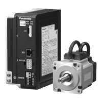
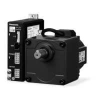
Installation of brushless motor
Oil and water protection
1) Direct down the lead of cable as far as possible.
2) Avoid use in such an environment where the motor is always exposed to oil and water.
3) Avoid use with cable immersed in oil or water.
Stress to cable
1) Make sure that stress is not applied to the lead or connection of cable due to bending or
dead weight.
2) In installation where the motor moves, x the cable of motor, and house the extension
cable connected to it in the cable bear to reduce stress by bending as small as possible.
3) Allow the bending radius of cable as large as possible.
Output shaft permissible load
1) The mechanical system should be so designed that the permissible radial load and
thrust load specied for a specic model will be supported by the shaft during installation
and operation.
2) When using rigid coupling, avoid application of unnecessary load. Excessive bending
load will cause breaking of shaft or shortening of bearing life.
3) Use a high rigid but exible coupling so that the radial load due to minute misalignment
is limited below the allowable value.
Installation guidelines
1) When installing a coupling to or removing a coupling from the motor shaft end, do not
apply shock directly to the shaft with e.g. a hammer.
2) Make an exact centering (incomplete alignment may cause vibration and damage the
bearing).
3) Do not allow operation that will cause the frame surface temperature to rise to 80 ℃ or
higher (ambient temperature at 40 ℃).
・
Geared shaft motor should be used with the gear head attached to it.
・
Round shaft motor should be used with its heat dissipated to the machine and equipment.
Installation Wiring
02
Connector
for control
signals (I/O)
External speed setting
Variable resister 5 kΩ
B characteristic 1/4 W
Brushless
amplifier
change of
Direction
10
1
01
+5V
FIN
GND
I3
I4
I5
I2
I1
Power
supply
input
L1
L2
L3
1
5
6
10
Be sure to ground the grounding terminal.
MCCB
Molded Case
(
Circuit Breaker
)
Grounding
Noise
filter
Brushless
amplifier
Power
supply
input
L1
L2
L3
1
5
6
10
Be sure to ground the grounding terminal.
MCCB
Molded Case
(
Circuit Breaker
)
Grounding
Noise
filter
Run/Stop
command
In wiring to power supply (outside of equipment) from MCCB, use an electric wire of 1.6 mm
diameter (2.0 mm
2
) or more both for main circuit and grounding.
Apply grounding class D (100 Ω or below) for grounding.
Do not tighten the ground wires together, but connect them individually.
Fastening torque of earth screws to be 0.49 to 0.98 N·m.
GV series
Forced trip
02
Connector
for control
signals (I/O)
10
1
01
+5V
(NC)
GND
I3
(NC)
I4
I2
I1
• In Case of 3-Phase 200 V
GP series
Run start
Point designation
Home sensor
Wiring
Standard wiring diagram
 Loading...