Do you have a question about the Panasonic NE-1257CR and is the answer not in the manual?
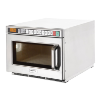
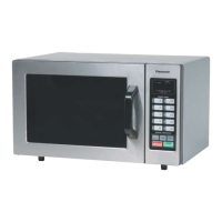
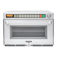
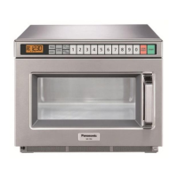
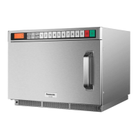
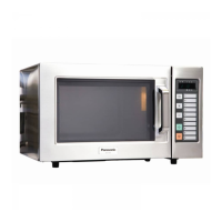
Lists the different commercial microwave oven models covered.
Details the required AC power source for operation.
Specifies the wattage and amperage for each model.
Shows the RF output power (HIGH, MED, LOW) for each model.
States the standard microwave frequency of 2,450 MHz.
Explains the maximum programmable time for heating stages.
Provides the width, depth, and height in inches and mm.
Gives the internal cavity dimensions in inches and mm.
Shows the weight of each model in lbs and kg.
Details safety measures to prevent microwave energy exposure during servicing.
Explains the function of the digital display window.
Details the display for power level indication.
Identifies the pad used for programming functions.
Identifies the pad used for shifting functions.
Identifies the buttons for selecting power levels.
Identifies the pad for double quantity cooking.
Identifies the pad for treble quantity cooking.
Identifies the pads for entering numbers and memory.
Identifies the pad for stopping or resetting functions.
Identifies the pad for starting operations.
Identifies the cover for the oven lamp.
Identifies the oven door handle.
Identifies the air filter component.
Identifies the splatter shield inside the cavity.
Step-by-step guide for manual heating in a single stage.
Guide for performing manual heating for two or three stages.
Details the process of heating using memory pads.
Guide for setting memory for two or three stage heating.
Explains how to heat using memory pads for double or treble quantity.
Instructions for selecting the length of the end-of-cycle beep tone.
Specifies circuit requirements and potential issues like shared circuits.
Instructions for selecting between 208V and 230V power sources.
Warning to unplug the oven before adjusting the voltage selector.
Reminder to verify wire colors and connector housing colors during replacement.
Reminder to verify wire colors and connector housing colors during replacement.
Reminder to verify wire colors and connector housing colors during replacement.
Reminder to verify wire colors and connector housing colors during replacement.
Reminder to verify wire colors and connector housing colors during replacement.
Reminder to verify wire colors and connector housing colors during replacement.
Explains how variable power cooking is controlled by relays.
Emphasizes the importance of proper grounding for operation and safety.
Warns against operating the oven with faulty door components due to leakage risk.
Warns about residual charge, high voltage parts, and discharge procedures.
Outlines essential safety steps before replacing parts, including fuse replacement.
Checks for loose screws, secure connections, and proper assembly after servicing.
Guards against foreign objects, radiation exposure, and exposed high voltage parts.
Step-by-step guide for replacing the upper and lower magnetrons.
Guides correct connection of filament lead wires to magnetron terminals.
Instructions for disconnecting positive lock connectors.
Steps for removing and replacing the power supply circuit board.
Steps for removing and replacing the digital programmer circuit board.
Warns that upper and lower antennas are not interchangeable.
Step-by-step guide for replacing the upper antenna.
Guides for replacing the floor shelf and lower antenna.
Steps for replacing the temperature sensor (thermal protector).
Step-by-step guide for disassembling the oven door assembly.
Instructions for mounting the door, including adjustment for alignment and play.
Procedure for testing the high voltage transformer's continuity and resistance.
Procedure for testing the high voltage capacitor's continuity and resistance.
Procedure for checking magnetron continuity for filament and shorts.
Procedure for testing diode front-to-back resistance.
How to check continuity of keyboard switch terminals.
Procedure for testing protector diode continuity.
Details the function and testing of the temperature sensor.
Warning about using identical replacement parts for radiation protection.
Instructions for installing safety and short switches.
Guidance on adjusting the door hook assembly for proper door fit.
Method to measure microwave output power using a water load test.
Lists necessary equipment for measuring microwave leakage.
Detailed steps for measuring leakage and recording results.
Recommends annual calibration of the radiation monitor.
General safety precautions before troubleshooting.
Addresses issues where the oven fails to operate or start cooking.
| Brand | Panasonic |
|---|---|
| Model | NE-1257CR |
| Category | Microwave Oven |
| Language | English |