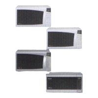
Do you have a question about the Panasonic NN-5856B and is the answer not in the manual?
Details the control panel layout and features for the NN-5856 microwave oven model.
Describes the control panel layout and functions for the NN-5556 and NN-5506 microwave oven models.
Explains the control panel layout and functions for the NN-5456 and NN-5406 microwave oven models.
Details the control panel layout and specific features for the NN-5256 microwave oven model.
Illustrates the internal wiring connections for the touch control models, detailing component interconnections.
Explains the operation of power cooking using the digital programmer circuit for touch control models.
Details the operation of variable power cooking via the mechanical timer assembly.
Describes the operation sequence for cyclic defrosting using the digital programmer circuit.
Outlines the procedures for auto defrost and auto reheat cooking on touch control models.
Step-by-step guide for replacing the magnetron, including safety precautions.
Procedure for replacing the Digital Programmer Circuit (DPC) and membrane keyboard.
Instructions for replacing the timer assembly in mechanical timer models.
Guidance on replacing the low voltage transformer and power relays (RY1, RY2).
Procedure for replacing the temperature sensor (thermal protector) in touch control models.
Detailed steps for replacing the door assembly and ensuring proper alignment.
Instructions for removing and replacing the turntable motor assembly.
Procedure for replacing the steam sensor in touch control models.
Tests continuity of primary latch, secondary latch switches, and power relay B.
Procedure for testing the short switch and monitor circuit.
Checks continuity of the high voltage transformer windings.
Procedure for testing the high voltage capacitor's continuity and charge.
Checks continuity of magnetron filament terminals and case.
Procedure for testing diodes using an ohmmeter, checking forward and reverse resistance.
Checks continuity of membrane keyboard switches.
Procedure for testing the protector diode's resistance.
Tests the steam sensor and digital programmer circuit functionality.
Checks the thermistor resistance value of the temperature sensor.
Tests the variable power controller in mechanical models.
Guidance on adjusting latch switches and short switch for proper door closure.
Procedure for measuring microwave output power using a water heating test.
Lists extension cables used for servicing the DPC board assembly.
Details the DPC common checker and its associated cable for diagnostics.
| Brand | Panasonic |
|---|---|
| Model | NN-5856B |
| Category | Microwave Oven |
| Language | English |


