EasyManua.ls Logo

Panasonic NN-E245WB EPG User Manual

Panasonic NN-E245WB EPG
24 pages
To Next Page IconTo Next Page
Page #1 background imageLoading...
Page #1 background image
P/NO : 3828W5S5178
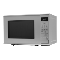
Microwave Oven
NN-E205WB BPQ
NN-E235MB BPQ
NN-E205WB EPG
NN-E245WB EPG
NN-E235MB EPG
NN-E205WB WPG
NN-E235MB WPG
NN-E205CB EPG
© 2005 Matsushita Electric (UK)Ltd.
All rights reserved. Unauthorized copying and
distribution is a violation of law.
Specifications
Power Requirement
Power Output
Microwave Frequency
Magnetron
Timer
Outside Dimensions
Cavity Dimensions
Net Weight
Shipping weight
230 Volts AC 50 Hz
1100 Watts
Single phase, 3 wire grounded
800 Watts full microwave power (IEC60705)
2450 MHz
2M167B - M47J1
0 ~ 60 min.
455 (W) x 252 (H) x 320 (D) mm
315 (W) x 203 (H) x 294 (D) mm
10.5 kg (approx.)
11.5 kg (approx.)
Specifications subject to change without notice.
Question and Answer IconNeed help?

Do you have a question about the Panasonic NN-E245WB EPG and is the answer not in the manual?

Panasonic NN-E245WB EPG Specifications

General IconGeneral
BrandPanasonic
ModelNN-E245WB EPG
CategoryMicrowave Oven
LanguageEnglish

Summary

SPECIFICATIONS

SAFETY PRECAUTIONS

PRECAUTIONS TO BE OBSERVED BEFORE AND DURING SERVICING

Precautions for safe servicing to avoid microwave energy exposure.

OPERATING INSTRUCTIONS

OPERATING SEQUENCE

Step-by-step guide for operating the microwave oven.

SERVICE INFORMATION

TOOLS AND MEASURING INSTRUMENTS

Lists necessary tools and instruments for servicing.

MICROWAVE LEAKAGE TEST

Procedure and precautions for testing microwave leakage.

MEASUREMENT WITH OUTER CASE REMOVED

Procedures for measuring leakage with the outer case removed.

MEASUREMENT WITH A FULLY ASSEMBLED OVEN

Procedures for measuring leakage with the oven fully assembled.

MEASUREMENT OF MICROWAVE POWER OUTPUT

Method for measuring the microwave oven's power output.

DISASBLY AND ADJUSTMENT

HIGH VOLTAGE TRANSFORMER REMOVAL

Steps to remove the high voltage transformer.

HIGH VOLTAGE CAPACITOR AND DIODE REMOVAL

Steps to remove the high voltage capacitor and diode.

MAGNETRON REMOVAL

Steps to remove the magnetron, including important notes.

INTERLOCK SYSTEM

Details on the interlock mechanism and switch mounting/adjustment.

INTERLOCK SWITCH TESTS

PRIMARY INTERLOCK SWITCH TEST

Tests for the primary interlock switch continuity and operation.

COMPONENT TEST PROCEDURE

TROUBLE SHOOTING

Related product manuals