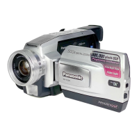
Do you have a question about the Panasonic NV-DS29B and is the answer not in the manual?
Crucial safety information regarding critical components and design modifications.
Procedures for performing cold and hot leakage current checks for safety.
Steps to drain static electricity before handling sensitive components.
Introduces the service manual's purpose, content, and ordering information.
Provides safety information related to AC cord usage and mains lead.
Step-by-step guide on how to replace the fuse in the mains plug.
Procedure for removing the Rear C.B.A. as the first step in battery replacement.
Steps to unsolder and replace the lithium battery with a new one.
General service notes and important considerations for technical personnel.
Specifies extension cables for service positioning and notes for check and service.
Lists palmcorder error codes that may indicate a need for service and troubleshooting guidance.
Explains the two types of Non ZIF connectors used in the unit.
Details the procedure and tool for removing/installing FPCs from Non ZIF connectors.
Step-by-step guide for ejecting the cassette with the power off.
Lists signals on the measuring board for electrical adjustment with descriptions.
Steps for removing a jammed tape using electrical methods.
Emphasizes saving EEPROM data before service using the PC-EVR Adjustment Program.
Steps for saving, writing, initializing EEPROM data, and inputting ID numbers.
Instructions on how to use the DVC head cleaning tape for maintenance.
Procedure for replacing the built-in light lamp, including safety precautions.
Procedures for disassembling the camera's cabinet.
Visual guide for the sequence of cabinet disassembly steps.
Key precautions for safe and effective disassembly and reassembly.
Procedures for disassembling and reassembling the camera's mechanism.
Diagram showing the location of inner parts from a top view perspective.
Diagram illustrating the location of inner parts from a bottom view perspective.
Lists the necessary service fixtures and tools required for adjustments.
Compares adjustment items with corresponding replacement parts.
Steps for adjusting the tension post, including required equipment and checks.
Steps for adjusting capstan tilt using the tilt adjustment tool and screws.
Overview of electrical adjustments and their relation to parts replacement.
Lists essential test equipment and specifications required for adjustments.
Outlines the initial preparation steps before commencing electrical adjustments.
Steps to set up and launch the PC-EVR adjustment program.
Describes the structure and navigation of the main menu within the adjustment program.
Important notes and guidelines pertaining to schematic diagrams and circuit board layouts.
Detailed schematic of the rear circuit board assembly.
Schematics for microphone, front, and EVF backlight circuits.
Schematic illustrating the LCD circuitry and connections.
Diagram showing the overall interconnections between major circuit boards.
Diagram illustrating the CCD drive system and its signal flow.
Block diagram showing the LCD system and its signal processing.
Diagram outlining the EVF system and its signal paths.
Block diagram detailing the power supply system and its voltage regulation.
Component layout for the rear circuit board assembly (dual patterns).
Component layouts for microphone, front, and EVF backlight circuit boards.
Component layout for the LCD circuit board assembly.
Exploded view of the main structural components of the camcorder.
Exploded views of the front case and lamp assembly sections.
Exploded view detailing the CCD and lens components.
Exploded view of the top case and EVF unit components.
Exploded view of the side case R and LCD display components.
Step-by-step guide for safely removing the cassette cover assembly.
Step-by-step guide for installing the cassette cover assembly, including setting tabs.
Covers removal of side case L unit, speaker, and installation of zoom switch FPC.
Guidelines for installing main C.B.A. and removing/installing rear C.B.A.
Installing the lens assembly, ensuring IR lever alignment.
Steps for removing and installing the top case and EVF assembly.
Instructions for mechanism chassis installation, CCD handling, and zoom motor unit installation.
Covers installation of EVF unit and EVF case assembly.
Steps for installing lens holder and eye sight levers, ensuring correct alignment.
Procedure for installing the LCD case assembly, including FPC and bosses alignment.
Procedures for removing LCD case B and installing LCD panel units with precautions.
Steps for correctly positioning and installing the lamp unit, with handling precautions.
Installing the Magic VU knob holder and knob into the front cover, ensuring correct orientation.
| Type | Camcorder |
|---|---|
| Optical Zoom | 10x |
| Digital Zoom | 500x |
| Microphone Operation Mode | Stereo |
| Display Type | LCD |
| Image Sensor | CCD |
| LCD Screen Size | 2.5 inches |
| Image Stabilizer | Electronic |
| Focus Adjustment | Auto/Manual |
| Microphone | Stereo |
| Connector Type | A/V output |
| Viewfinder Type | Color |
| Battery Type | Lithium-Ion |
| Viewfinder | Color |
| Recording Media | MiniDV |
| Video Recording System | Mini DV |
| Input/Output Terminals | A/V output |
| Power Supply | Battery, AC adapter |