32 – ENGLISH
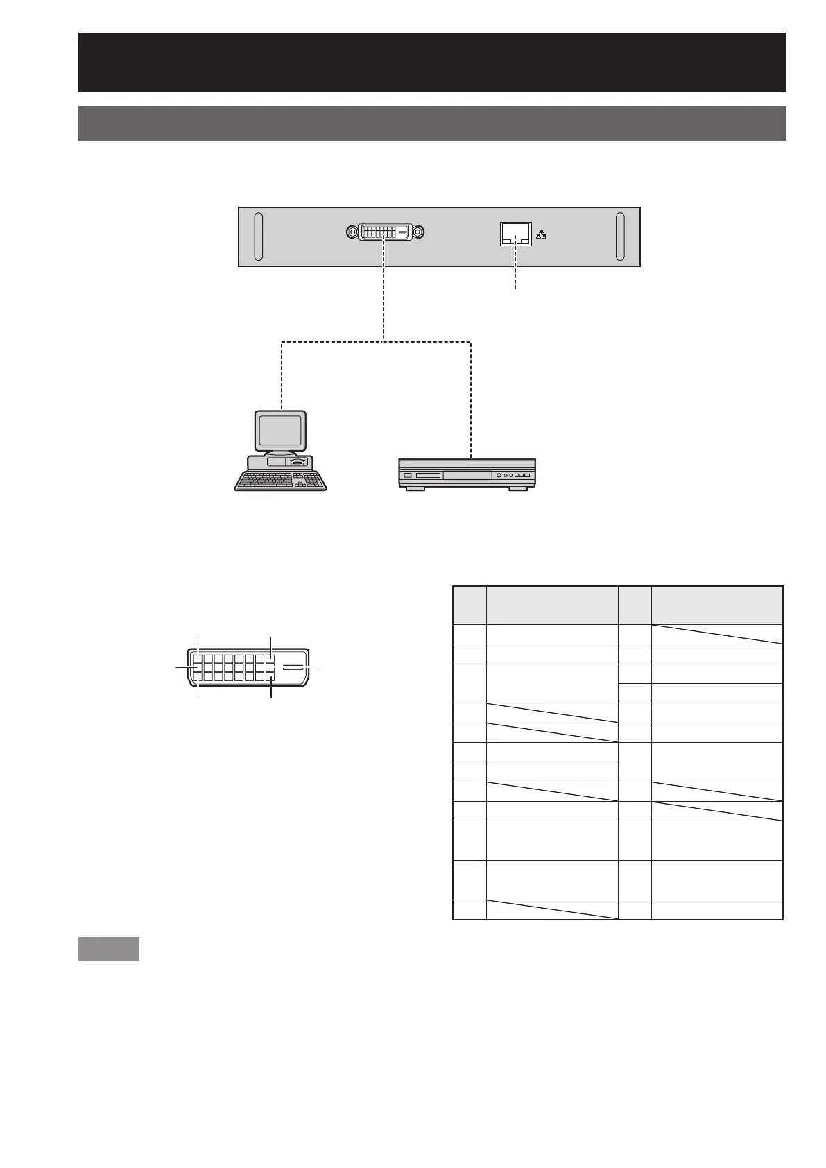
Connecting signals to the DVI-D input module
Note
The DVI-D signal input module supports only a single link.
The HDMI-DVI-D conversion cable is required to connect an HDMI-compliant device.
The EDID mode setting must be selected so that it corresponds to the device to be connected. (p. 72)
It is possible to connect the DVI-D input module with an HDMI- or DVI-D-compliant device, but with some devices
the images may not appear or other problems may be encountered in operation.
*1: The LAN terminal of the input module (optional) cannot be used with the PT-D10000U/PT-DW10000U. Use the
LAN terminal that is provided as standard with the projector.
•
•
•
•
DVI Module
ET-MD77DV
DVI-D IN LAN
DVI-D input module (optional)
ET-MD77DV
DVI-D signal
LAN terminal
*1
(10BASE-T/100BASE-TX)
DVD player or high-vision video
deck equipped with DVD/HDMI
terminal
PC with DVI output
DVI Module
ET-MD77DV
DVI-D IN LAN
DVI-D input module (optional)
ET-MD77DV
DVI-D signal
LAN terminal
*1
(10BASE-T/100BASE-TX)
DVD player or high-vision video
deck equipped with DVD/HDMI
terminal
PC with DVI output
Pin assignments and signal names of DVI-D input
terminal are listed in the table at right.
•
#+
=
4
5
-
Outside view
Pin
No.
Signal
Pin
No.
Signal
#
T.M.D.S data 2–
1
$
T.M.D.S data 2+
2
+5V
%
T.M.D.S data 2/
4 shield
3
Ground
4
Hot plug detection
&5
T.M.D.S data 0-
(6
T.M.D.S data 0+
)
DDC clock
7
T.M.D.S data 0/
5 shield
*
DDC data
+8
-
T.M.D.S data 1–
9
.
T.M.D.S data 1+
:
T.M.D.S clock shield
/
T.M.D.S data 1/
3 shield
;
T.M.D.S clock+
0=
T.M.D.S clock–
Installation of input module (optional) (continued)
 Loading...