counterclockwise.
5. Eject the cassette by applying +10.0 V DC Power Supply again.
5.1.9. VCR Test Mode
High Voltage is inhibited by connecting Jumper J801 on the TV/VCR Main C.B.A., however, it is
possible to check the VCR even when CRT C.B.A. and Anode Cap are removed.
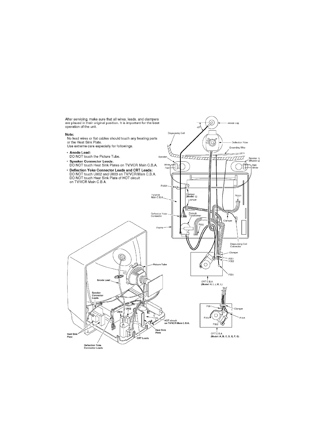
5.1.10. WIRE AND LEAD POSITION DIAGRAM
Fig. 8
5.1.11. DEFEATING THE AUTO TRACKING
To defeat the Auto Tracking Function, place the instrument in the STOP mode and place a jumper
between TP6003 and TP6009 on the TV/VCR Main C.B.A. The tracking will be placed in the neutral
position.
18
 Loading...