EasyManua.ls Logo

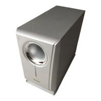
Panasonic Ramsa WS-A240

Panasonic Ramsa WS-A240
14 pages
To Next Page IconTo Next Page
To Previous Page IconTo Previous Page
Loading...
RACK
MOUNTING
BRACKETS
A.
1
Unit
Mounting
Bracket
fixing
screws
(accessory)
M4
x
8
1.
Remove
4
rubber
feet.
d
à
Fix
the
rack
mounting
brackets
A
and
B
{standard
accessory)
to
the
Subwoofer
processor
with
the
attached
screws.
3.
Mount
the
Subwoofer
processor
to
the
rack.
Bracket
A:
part
No.
A2SA1036A4
Bracket
B:
part
No.
A28A1037B3
Rack
manting
Bracket
A
|
Screws
e
(not
provided)
Rubber
feet
7
B.
2
Units
Mounting
(not
provided)
Remove
8
rubber
feet.
Fix
two
processors
with
bracket
C
and
screws.
Fix
the
rack
mounting
brackets
to
the
both
sides
of
the
processor
with
the
attached
screws.
Mount
the
processor
to
the
rack.
e
SN
Bracket
fixing
screws
{accessory}
M4
x
8
Mounting
screws
M4
x
8
(not
provided)
Flush
head
machine
screws
MA
x
B
Bracket
A:
part
No.
A2SA1036A4
Bracket
C:
part
No.
A2SA1038A4
Rubber
feet
F.
:
q^
VA
$
f
Z
Caution:
Don't
use
screws
longer
A.
|
Bracket
A
Nang
than
8
mm.
LOE
Z
~
Bracket
C
Rack
mounting
screws
$
L
not
provided)
inot
provided)
TYPICAL
APPLICATIONS
SYSTEM
A
Illustrated
are
two
WS-A10
Compact
Speaker
Systems
in
a
two
channel
configuration,
powered
by
one
WP-9055
am-
plifier.
The
single
WS-A240
Subwoofer
is
powered
by
one
WP-9110
amplifier
in
the
bridge
(BTL)
mode.
The
WS-
SP2A
Subwoofer
Processor
should
be
adjusted
(by
quali-
fied
service
personnel
only)
for
WS-A10/WS-A240
signal
processing.
A
Dut
B
Out
LE
Out
WP-9055
WS.SP2A
Subwoofer
Processor
Main
Out
L
WS-A240
Subwoofer
CS
RE
Sku
WP-9110
1BTL)
Main
Out
R

Related product manuals