Do you have a question about the Panasonic SB-WA340 and is the answer not in the manual?
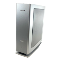
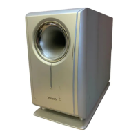
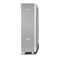
Key technical parameters of the active subwoofer system, including electrical and physical characteristics.
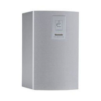
Details compatible system configurations, such as SC-HT1000EBS and SC-HT1000EGS.
Outlines fundamental safety rules, protective measures, and general guidelines for safe servicing.
Details procedures for performing cold and hot checks to measure electrical leakage current for safety.
Provides instructions for safely handling and soldering with lead-free solder, including temperature requirements.
Lists essential steps to take before commencing repair or adjustment, including power discharge.
Explains the purpose and conditions under which the protection circuitry may activate to prevent damage.
Guides on correctly connecting speaker cables to the unit, ensuring proper polarity and impedance.
Provides a step-by-step guide for disassembling the subwoofer unit for servicing or component access.
Step-by-step instructions for desoldering and replacing the Power IC component on the Power PCB.
Illustrates the correct wiring connections for the speaker cables, showing polarity for red and black wires.
Presents a high-level block diagram illustrating the main functional units and their interconnections.
Contains detailed schematic diagrams of the unit's electronic circuits for in-depth analysis.
Provides layout diagrams of the main printed circuit boards, showing component positions and connections.
Offers visual representations and pinouts for integrated circuits, transistors, and diodes used in the unit.
Shows the physical location and reference numbers for all cabinet-related parts.
A comprehensive list detailing all cabinet parts, including part numbers and descriptions.
Lists the specific materials used for packaging the product, such as foam and protective wraps.
Illustrates how the product is packaged for shipping and handling, showing the placement of packing materials.
Detailed schematic diagram of the power circuit, showing component interconnections and signal paths.
Continues the detailed schematic for the power circuit, illustrating further component interconnections and signal paths.
Provides schematics for the transformer circuit and the AC inlet circuit, detailing their functionality.