Do you have a question about the Panasonic SB-WA880 and is the answer not in the manual?
General guidelines for servicing, including lead dress, protective devices, and leakage current checks.
Procedure for checking leakage current with the unit unplugged, measuring resistance between plug and cabinet parts.
Procedure for checking leakage current with the unit plugged in, using a resistor/capacitor network and AC voltmeter.
Information on lead-free solder, its melting point, and precautions for use with high-temperature soldering irons.
Outlines the procedure for disassembling the casing and internal parts for inspection.
Details the step-by-step process for removing the front panel unit from the subwoofer cabinet.
Step-by-step process for removing the front panel unit from the subwoofer cabinet.
Instructions for disassembling and removing the first woofer speaker from the unit.
Instructions for disassembling and removing the second woofer speaker from the unit.
Procedure for disassembling the power amplifier unit from the subwoofer.
Steps to remove the rear panel and the unit's fan.
Procedures for disassembling and checking the AC inlet and amplifier PCBs.
Procedures for disassembling and checking the power and transformer PCBs.
Instructions for replacing power integrated circuits (ICs) and transistors.
Explains how to measure voltages and the importance of using specified equipment and conditions.
Discusses waveform measurements as reference information for defect point analysis.
Details the schematic diagram for the power circuit of the unit.
Presents schematic diagrams for the transformer and AC inlet circuits.
Provides the schematic diagram for the amplifier circuit.
Information regarding the Power Printed Circuit Board (P.C.B.).
Details the AC Inlet and Transformer Printed Circuit Boards (P.C.B.s).
Information pertaining to the Amplifier Printed Circuit Board (P.C.B.).
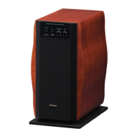
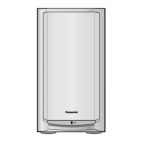
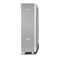
Illustrates the location of cabinet parts with reference numbers.
List of cabinet parts with their corresponding part numbers.
Comprehensive list of electrical components and their part numbers.
Detailed schematic of the power circuit for the unit.
Continuation of the power circuit schematic, including regulators and filters.
Schematic diagram for the transformer circuit.
Schematic diagram for the AC inlet circuit.
Schematic diagram for the amplifier circuit, showing transistors and ICs.