EasyManua.ls Logo

Panasonic SB-WA535EE User Manual

Panasonic SB-WA535EE
32 pages
To Next Page IconTo Next Page
Page #1 background imageLoading...
Page #1 background image
n Active subwoofer
Type 1 way, 2 speaker system (Bass
reflex)
Speaker unit(s)
1. Woofer 13 cm Cone type
2. Woofer 13 cm Cone type
Output sound pressure level 80 dB/W (1.0 m)
Frequency range 40 Hz-220 Hz (-16 dB)
45 Hz-180 Hz (-10 dB)
Dimensions (W x H x D) 201.5 x 368.2 x 491.5 mm
Mass 11.3 kg
n General
Power consumption 250 W
Power supply AC 230V, 50Hz
1 Safety Precautions
3
1.1. GENERAL GUIDELINES
3
2 Handling the Lead-free Solder
4
2.1. About lead free solder (PbF)
4
3 Before Repair and Adjustment
4
© 2005 Matsushita Electric Industrial Co. Ltd.. All
rights reserved. Unauthorized copying and
distribution is a violation of law.
SB-WA535EE
Colour
(S)... Silver Type
n System : SC-HT535 (EE)
Music Center: SA-HT535 (EE)
Satellite Speakers: SB-HT535 (EG)
Active Subwoofer: SB-WA535 (EE)
Note :
Specifications are subject to change without notice.
Mass and dimensions are approximate.
4 Protection Circuitry 4
5 Connection of the Speaker Cables
5
6 Disassembly Procedure
6
6.1. Disassembly flow chart
6
Active Subwoofer System
Specification
CONTENTS
Page Page
ORDER NO. MD0507276C3
Question and Answer IconNeed help?

Do you have a question about the Panasonic SB-WA535EE and is the answer not in the manual?

Panasonic SB-WA535EE Specifications

General IconGeneral
BrandPanasonic
ModelSB-WA535EE
CategorySubwoofer
LanguageEnglish

Summary

Specification

Active Subwoofer Specifications

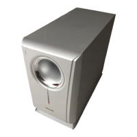
Detailed technical specifications for the active subwoofer unit.

General System Information

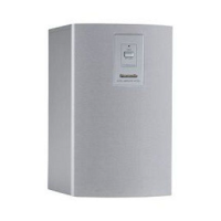
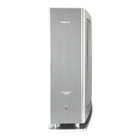
General system information and related model numbers.

Safety Precautions

General Guidelines

Basic rules and advice for safe servicing of the unit.

Leakage Current Cold Check

Procedure to check for leakage current with power off using an ohmmeter.

Leakage Current Hot Check

Procedure to check for leakage current with power on using an AC voltmeter.

Handling Lead-free Solder

About Lead-free Solder (PbF)

Guidance on handling and soldering lead-free solder.

Before Repair and Adjustment

Protection Circuitry

Connection of Speaker Cables

Disassembly Procedure

Disassembly Flow Chart

Visual guide outlining the sequence for disassembling the unit's components.

Speaker Unit Disassembly and PCB Checking

Detailed steps for disassembling the speaker unit and checking PCBs.

Voltage Measurement and Waveform Chart

Voltage Measurement

Table of standard voltage values at various test points for diagnosis.

Waveform Chart

Visual representations of normal signal waveforms at key points.

Block Diagram

Notes of Schematic Diagram

Schematic Diagram

Power Circuit

Detailed schematic of the unit's power supply and distribution circuit.

Transformer and AC Inlet Circuits

Schematics for the transformer and AC power input sections.

Printed Circuit Board

Power P.C.B.

Layout and identification of components on the Power PCB.

AC Inlet and Transformer P.C.B.s

Layout and identification of components on AC Inlet and Transformer PCBs.

Wiring Connection Diagram

Illustration of ICs, Transistors and Diodes

Parts Location and Replacement Parts List

Cabinet Parts

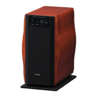
Diagrams and lists for cabinet components and their locations.

Electrical Parts List

Comprehensive list of electrical components with part numbers and descriptions.

Packing Materials & Accessories Parts List

List of packing materials and accessories included with the unit.

Packaging

Illustration of how the unit is packaged for shipment.

Related product manuals