7 Voltage Measurement and Waveform Chart
Note:
·
Indicated voltage values are the standard values for the unit measured by the DC electronic circuit tester (high-impedance)
with the chassis taken as standard.
Therefore, there may exist some errors in the voltage values, depending on the internal impedance of the DC circuit tester.
·
Circuit voltage and waveform described herein shall be regarded as reference information when probing defect point
because it may differ from actual measuring value due to difference of Measuring instrument and its measuring condition
and product itself.
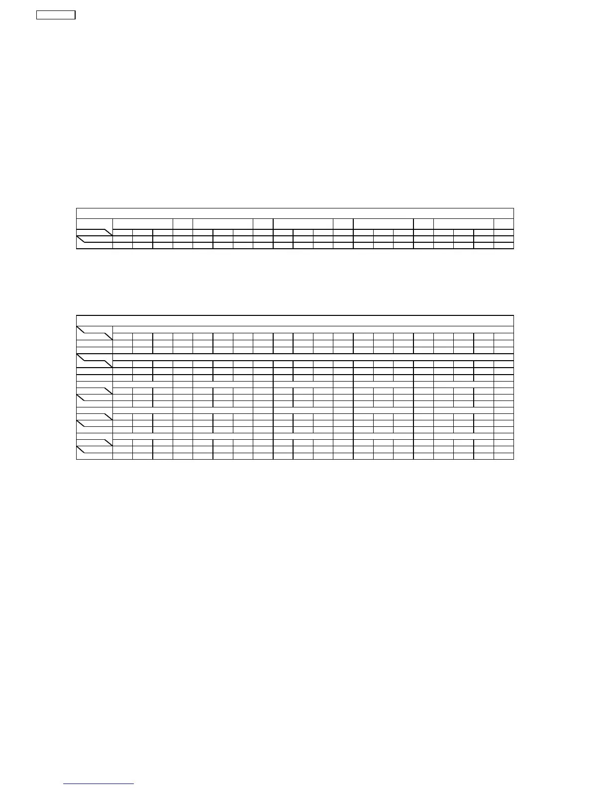
7.1. Voltage Measurement
7.1.1. AC Inlet P.C.B.
Ref No.
MODE E C B E C B E C B E C B
CD PLAY 0.1 0.1 0.8 0.1 3.6 -0.2 6.0 13.0 6.7 0.1 0.8 0
STANDBY 0 6.0 0 0 3.6 -0.3 6.0 11.7 6.6 0 0 0
Q515
AC INLET P.C.B.
Q516 Q519Q517
7.1.2. Power P.C.B.
Ref No.
MODE 1234567891011121314151617181920
CD PLAY 0 0 66.0 -65.8 0 32.4 -32.6 000000-0.2 32.7 -32.8 -10.3 0 0 66.0
STANDBY 0 0 11.9 0.3 00000000000000011.9
Ref No.
MODE 21 22 23 24 25 26
CD PLAY -65.9 00000
STANDBY 0.3 00000
Ref No.
MODE E C B E C B 1 2 3 E C B E C B
CD PLAY 0 5.2 0 0 5.2 0 0 0 -1.1 0 0.8 0 0.8 0 0.8
STANDBY 0 0.9 0 0 0.9 0 0 0 0 0 0 0 0 0 0
Ref No.
MODE E C B E C B E C B E C B E C B
CD PLAY 5.1 32.7 5.6 -11.5 -32.7 -12.1 0 -0.7 0 0 -11.5 0.2 -11.5 5.0 -11.5
STANDBY 0.5 0 0 0 0 0 0 0 0 0 0 0 0 0.5 0
Ref No.
MODE E C B E C B E C B E C B
CD PLAY 5.1 - 4.6 4.7 5.1 - 0 0.4 -0.2 0.4 5.2 0
STANDBY 0.5 0 0.1 2.3 0.5 0 0 0.3 0 0.3 0.9 0
Q512 Q553
Q556
Q520 Q552
Q503
Q554 Q555 Q557
Q501
Q511
POWER P.C.B.
IC501
IC501
Q502 Q505 Q506
14
SB-WA535EE
 Loading...