Do you have a question about the Panasonic SB-WA935 and is the answer not in the manual?
Crucial warning about servicing by experienced technicians only.
General advice for servicing, including lead dress and protective device installation.
Procedures for both cold and hot checks to prevent shock hazards.
Instructions on power disconnection, capacitor discharge, and gradual power restoration.
Explains when protection circuitry operates and how to reset it.
Procedure for disassembling and inspecting the AC inlet and amplifier PCBs.
Procedure for disassembling and inspecting the power and transformer PCBs.
Instructions for replacing power ICs and transistors.
Highlights components with special safety characteristics and replacement parts.
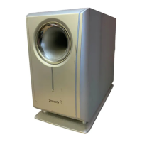
| Type | Active |
|---|---|
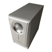
| Driver Size | 8 inches |
| Frequency Response | 30 Hz - 200 Hz |
| Inputs | Line in |
| Outputs | Line out |