Do you have a question about the Panasonic RQ-S75 and is the answer not in the manual?
Details the power sources for the unit, including batteries and external adapters.
Specifies the audio output power and headphone jack impedance.
Lists the physical dimensions and approximate weight of the cassette player.
Details charger specifications and frequency response for different tape types.
Identifies the motor type and tape playback speed.
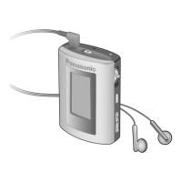
Identifies and describes the controls and indicators on the main cassette player unit.
Details the controls and features of the stereo earphones with remote.
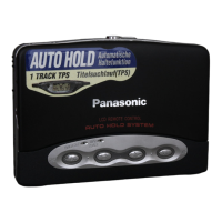
Explains the auto hold feature and how to operate it.
Lists and illustrates the accessories provided with the cassette player.
Instructions for charging and using the rechargeable battery.
Instructions for inserting and using dry cell batteries.
Explains the function of the use time indicator for battery life.
How to use the remote control for tape playback, stop, fast forward, and rewind.
How to adjust sound tone and activate LIVE effect using the remote.
Guidance on adjusting the volume using the remote control.
Step-by-step guide for replacing the entire mechanism block.
Instructions for replacing the head block, including the pinch roller.
Steps to remove the main mechanism unit from the device.
Detailed steps for removing the head block and pinch roller.
Procedure for removing the motor and drive belt from the mechanism.
Step-by-step guide to remove the outer cabinet assembly.
Procedure for detaching and removing the main printed circuit board.
Steps to remove the open lever assembly.
Procedure for removing the cam lock unit.
Steps to remove the leaf switch component.
Procedure for detaching the cassette lid assembly.
Steps to remove the intermediate cabinet part.
Procedure to remove the switch printed circuit board.
Steps to remove the operation buttons, plate, and frame.
Procedure for removing cassette lid link units and plates.
Steps to remove the headphone jack holder and control knobs.
Important notes and steps for correctly assembling the main PCB onto the mechanism block.
Detailed instructions for assembling the cassette lid A and its link units.
Procedure for assembling the open lever assembly onto the unit.
Steps to assemble the cassette lid assembly with the main cabinet.
Guide on how to check unit operations during disassembly and servicing procedures.
General guidelines and preparation steps before performing adjustments.
Specifies control settings and equipment needed for measurements and adjustments.
Details on adjusting tape speed and related parameters.
Identifies specific points on the schematic and PCB for short-circuiting during testing.
Presents the overall circuit diagram for the device.
Shows the functional blocks and signal flow within the device.
Detailed schematic of the main electronic circuits, including ICs and transistors.
Schematic detailing the switch circuit functions.
Diagram showing component placement and connections on the main PCB.
Diagram illustrating the layout of the head PCB.
Diagram showing component placement on the switch PCB.
Identifies test points and terminal guides for ICs, transistors, and diodes.
Details the function of each terminal for the mechanism control IC.
Lists replacement parts for the cabinet and chassis components.
Lists various other replacement parts including screws, plates, and springs.
Lists replacement parts for ICs and transistors used in the unit.
Lists replacement resistor and capacitor values and part numbers.
Lists replacement capacitor values and part numbers.
Illustrates the location and numbering of parts within the device cabinet.
Identifies components within the mechanism block assembly.
Instructions on how to apply the mechanism sheet correctly.
Illustrates the components included in the packaging for the unit.
| Type | Portable Cassette Player |
|---|---|
| Brand | Panasonic |
| Model | RQ-S75 |
| Category | MP3 Player |
| Power Source | Battery |
| Battery | Rechargeable Ni-Cd |
| Features | Auto-reverse |