4.1. Schmatic Diagram Notes
(This schematic diagram may be modified at any time with
development of new technology.)
·
S1 : Stop switch (
).
·
S2 : Playback switch (
).
·
S3 : Fast forward switch (
).
·
S4 : Rewind switch(
).
·
S5 : Folder, Menu switch (
).
·
S6 : Recording mode switch (REC MODE).
·
S7 : Erase switch (ERASE).
·
S8 : Recording/Stop switch (REC/STOP).
·
S9 : Volume (+) switch.
·
S10 : Volume (-) switch.
·
S13 : Hold switch (HOLD) in “OFF” position.
·
S14: Batt. cover open det. switch.
·
S18: Meeting/Dictation select switch
(MEETING/DICTATION) in “MEETING” position.
·
Important safety notice
Components identified by
; mark have special
characteristics impotant for safety.
When replacing any of components, use only
manufacturer’s specified parts.
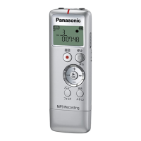
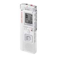
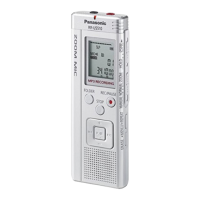
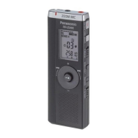
4 Schematic Diagram
4
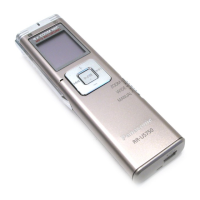
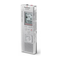
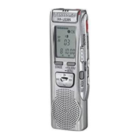
RR-US395PC / RR-QR180P / RR-QR180PC / RR-QR170P