EasyManua.ls Logo

Panasonic RS-B25 User Manual

Panasonic RS-B25
42 pages
To Next Page IconTo Next Page
Page #1 background imageLoading...
Page #1 background image
Spiiionna
amps
cS
m
Wa
OGRE
IN
Tat
omnmar
rms.
ORDER
NO.
HAD85042533C8
Service
Manual
Dal
DOLBY
B-C
NR
|
Dolby
B
«
C
NR-Equipped
Stereo
Cassette
Deck
RS-B25
MECHANISM
SERIES
SPECIFICATIONS
Deck
system
Track
system
Heads
REC/PLAY
Erasing
Motor
Recording
system
Bias
frequency
Erasing
system
Tape
speed
Frequency
response
Metal
CrOz
Normal
Stereo
cassette
deck
4-track,
2-channel
MX
head
Doubie-gap
ferrite
head
1
motor
system
AC
bias
80
kHz
AC
bias
4.8
cm/sec.
20
Hz~17,000
Hz
30
Hz~17,000
Hz
(DIN)
40
Hz~16,000
Hz+3
dB
20
Hz~17,000
Hz
30
Hz~16,000
Hz
(DIN)
40
Hz~15,000
Hz+3
dB
20
Hz~
16,000
Hz
30
Hz~
15,000
Hz
(DIN)
40
Hz~14,000
Hz+3
dB
S/N
(Signal
level=max.
recording
level,
CrOz
type
tape)
Dolby
B
NRin
Doiby
C
NRin
NR
out
67
dB
(CCIR)
75
dB
(CCIR)
57
dB
(A
weighted)
Cassette
Deck
RS-B25
Color
|
(K)...Black
Types
|
(S)...Silver
Type
|
Area
|
_
———
ca
:
(K)
Gy
TE)
22.
All
European
areas
|
|
except
United
|
Kingdom.
|
P
[EKPA8
United
Kingdom.
|
[EH]......Holland.
|
[EGA]...F.R.
Germany.
|
[XA]...
Asia,
Latin
America,
Middle
|
East
and
Africa.
i
(K)
(S)
[XL].......
Australia.
|
Wow
and
flutter
0.07%
(WRMS)
13%
(DIN)
Fast
Forward
and
Rewind
Time
Approx.
90
seconds
with
C-60
cassette
tape
input
sensitivity
and
impedance
MIC
0.25
mV/4000~10
kQ
LINE
60
MV/47
kQ
Output
voltage
and
impedance
:
LINE
400
mV/1.5
kQ
HEADPHONES
80
mV/8Q
Power
consumption
16W
Power
supply
JEERTEGA,
AC;
220V,
50Hz/60
Hz
PERI
Seon
cgianten
dhedvre
atieeeene
cation
a
AC;
240V,
50Hz/60
Hz
PRA]
sc
codecr
testes
cece
AC;
110V/127V/220V/240V,
50
Hz/60
Hz
Preset
power
voitage
240V
Dimensions
(WxHxD)
430x99.5x229mm
Weight
3.4kg
Design
and
specifications
are
subject
to
change
without
notice.
‘Dolby’
and
the
doubie-D
symbol
are
trademarks
of
Dolby
Laboratories
Licensing
Corporation.
Technics
Matsushita
Electric
Trading
Co.,
Ltd.
P.O.
Box
288,
Central
Osaka
Japan
Question and Answer IconNeed help?

Do you have a question about the Panasonic RS-B25 and is the answer not in the manual?

Panasonic RS-B25 Specifications

General IconGeneral
BrandPanasonic
ModelRS-B25
CategoryCassette Player
LanguageEnglish

Summary

Product Specifications

Deck System and Heads

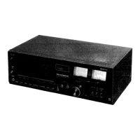
Details the cassette deck's mechanical setup and head configuration.

Performance Metrics

Covers wow/flutter, fwd/rewind time, input/output sensitivity, and headphone specs.

Power and Dimensions

Lists power consumption, supply, dimensions, and weight.

Color and Area Options

Specifies available color choices and regional market variations.

Disassembly Procedures

Case Cover Removal

Step-by-step guide for removing the outer case cover.

Front Panel Assembly Removal

Instructions for detaching the front panel assembly.

PCB and Module Removal

Procedures for removing the main PCB and other internal modules.

Mechanism Unit Extraction

Steps to safely remove the internal mechanism unit.

Connector and Cable Handling

Guidance on disconnecting and handling flat cables and connectors.

Measurements and Adjustments

Tape Speed Calibration

Procedures for adjusting and measuring tape speed accuracy.

Head Alignment and Balance

Adjusting head azimuth, L-CH/R-CH output balance, and phase.

Frequency Response Testing

Measuring and adjusting playback and overall frequency response.

Erase Current Adjustment

Procedure for measuring and adjusting the erase current.

Gain and Meter Calibration

Adjusting overall gain and calibrating the LED meter.

Dolby NR Circuit Performance

Checking and adjusting the Dolby B and C NR circuit characteristics.

Microcomputer Terminal Functions

Record/Playback Status Signals

Describes PD, PD1, PD2, PD3 terminals for record/playback status.

Mechanism Control Signals

Details OSC, PEΦ, PE1, PE2, PE3 terminals for mechanism operation.

System Control Terminals

Explains TEST, Vss, INT, RST, VDD terminals for system control.

Key Input Terminals

Covers PAΦ, PA1, PA2, PA3 terminals for various key inputs.

Input Scanning Terminals

Details PC, PC1, PC2, PC3 terminals related to input scanning.

Block Diagram

Electrical Parts List

Schematic Diagram

Circuit Board and Wiring Diagrams

Dolby NR PCB Layout

Wiring and component layout for the Dolby NR circuit board.

Mechanism PCB Layout

Wiring and component layout for the mechanism control PCB.

Main PCB Layout

Wiring and component layout for the main processing PCB.

LED Meter PCB Layout

Wiring and component layout for the LED meter indicator PCB.

Technical Guide: Mechanism Operation

STOP → PLAY OPERATION

Explains the basic operation sequence from STOP to PLAY mode.

Mechanical Parts Location

Front View Exploded Diagram

Illustrates the location of mechanical parts from the front.

Back View Exploded Diagram

Illustrates the location of mechanical parts from the back.

Terminal Guide for Components

Cabinet Parts Location

Related product manuals