EasyManua.ls Logo

Panasonic RS-612US-D User Manual

Panasonic RS-612US-D
24 pages
To Next Page IconTo Next Page
Page #1 background imageLoading...
Page #1 background image
ORDER
NO.
ARD-7706053C
ervice
Manual
Cassette
Deck
RS-612US-D
Front
Loading
Stereo
Cassette
Deck
with
Dolby*
Noise-Reduction
System,
Timer
Stand-By,
and
Bias
and
Equalization
Switches
Specifications
(Catalog
specifications
for
sales)
Power
requirement:
AC;
90~109/110~125/200~219/220
~250V,
50/60
Hz
Power
consumption;
11
W
Motor:
1-electronic
speed
contro!
motor
4-track,
2-channel
stereo
recording
and
playback
Track
system:
Tape
speed:
4.8cm/s
Wow
and
flutter:
0.12%
(WRMS),
+0.25%
(DIN)
Frequency
response:
CrOz
tape;
30~15,000Hz
40
~
14,000
Hz
(DIN)
Normal
tape;
30
~
13,000
Hz
40
~
12,000
Hz
(DIN)
Signal-to-noise
ratio:
Dolby
NR
in;
65 dB
(above
5kHz)
Dolby
NR
out;
55dB
(signal
level=
max.
recording
level)
Fast
forward
and
rewind
time:
Input
:
Head:
Dimensions:
Weight:
Approx.
90
seconds
with
C-60
cassette
tape
MIC;
sensitivity
0.25
mV/applicable
microphone
impedance
4002
~
20
KQ
LINE;
sensitivity
60
mV/input
impedance
90
KQ
DIN;
sensitivity
0.25
mV/input
impedance
1.8KQ
LINE;
output
level
420
mV/load
impedance
22
KQ
over
2-head
system
1-super
permalloy
head
for
record/playback
1-double-gap
ferrite
head
for
erasure
41.0cm(W)
X
13.6cm(H)
x
24.4cm(D)
Akg
Specifications
are
subject
to
change
without
notice.
National
Panasonic
Matsushita
Electric
Trading
Co.,
Ltd.
P.O.
Box
288,
Central
Osaka
Japan
Question and Answer IconNeed help?

Do you have a question about the Panasonic RS-612US-D and is the answer not in the manual?

Panasonic RS-612US-D Specifications

General IconGeneral
BrandPanasonic
ModelRS-612US-D
CategoryCassette Player
LanguageEnglish

Summary

Specifications

Technical Specifications Summary

Lists key parameters like power, motor, tape speed, frequency response, and noise ratio.

Location of Controls and Components

Front Panel and Rear Connections

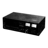
Identifies front panel controls, buttons, knobs, and rear/side panel connectors.

Disassembly Instructions

Component Removal Procedures

Outlines steps for disassembling main parts with reference to figures.

Adjustments

Test Instruments and Specifications

Lists required test equipment and their technical specifications for calibration.

Instrument Specifications

Details specifications for attenuator, oscilloscope, digital counter, and wow meter.

Test Procedures and Conditions

Measurement Conditions and Environment

Specifies ambient conditions, power voltage accuracy, and positioning for testing.

Test Tape Usage Guidelines

Details types of test tapes and their recommended usage frequency and storage.

Measurement and Adjustment Methods

Mechanical Adjustments

Procedures for measuring and adjusting pressure roller tension and takeup tension.

Head Alignment and Tape Speed

Methods for head azimuth adjustment and tape speed calibration.

Tape Speed and Wow/Flutter Measurement

Procedures for measuring tape speed accuracy, fluctuation, and wow/flutter.

Playback Performance Measurements

Methods for measuring playback frequency response, gain, and signal-to-noise ratio.

Recording Performance Measurements

Procedures for measuring and adjusting bias current and erase current.

Overall Performance Measurements

Methods for measuring overall gain, level meter indication, and distortion.

Frequency Response Charts and Measurement

Provides frequency response charts and measurement steps for different tape types.

Advanced Adjustments and S/N Ratio

Adjusting frequency response via bias, measuring S/N, and Dolby NR circuit calibration.

Adjustment Parts Location

Component and VR Adjustment Diagrams

Diagrams showing adjustment points on the PCB and locations of variable resistors.

Schematic Diagram

Circuitry Overview

Detailed electrical schematic showing left/right channels and common circuits.

Wiring Connection Diagram

Wiring Layout and Connections

Illustrates the wiring connections for the main board and external components.

Exploded Views

Mechanical Assembly Layouts

Diagrams showing exploded views of the unit's mechanical assemblies.

Detailed Mechanism Sub-assemblies

Exploded views of specific mechanical sub-assemblies for detailed part identification.

Parts Location Diagrams

Electrical and Cabinet Component Layouts

Diagrams showing the physical locations of electrical components and cabinet parts.

Replacement Parts List

Mechanical Parts Listing

Comprehensive list of mechanical parts with part numbers and descriptions.

Mechanical Parts Details (M1-M24)

Continues the mechanical parts list, detailing base plates, levers, and rollers.

Electronic Components Listing

Lists variable resistors, capacitors, transistors, and diodes with part numbers.

Mechanical Parts (M91-M98) and Resistors

Lists remaining mechanical parts and resistors with their specifications.

Transformers, Switches, Electrical Parts, Cabinet Parts

Lists transformers, switches, electrical components, and cabinet parts.

Final Cabinet Parts, Accessories, Packings

Lists remaining cabinet parts, accessories, and packing materials.

Related product manuals