EasyManua.ls Logo

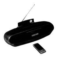
Panasonic RX-DS45

Panasonic RX-DS45
58 pages
To Next Page IconTo Next Page
To Previous Page IconTo Previous Page
Loading...
RX-DS45
PREPARATION
FOR
SERVO
GAIN
ADJUSTER
Using
the
new
version
of
the
servo
gain
adjuster
(SZZP1094C-1)
a
(For
tracking
gain,
focus
gain
and
tracking
balance
adjustments.)
Test
connector
(SZZPIIO5C)
Adaptor
B
(SZZPI104)
COP.C.B.
Yay
(Rear
Side)
fl
CP705
Servo
gain
Indicator
5
(V-REF)
eCONNECTING
THE
OSCILLOSCOPE
(Mechanical
adjustment
and
adjustment
of
the
best
eye,
focus
offset,
tracking
offset
and
tracking
balance)
Oscilloscope
connection
terminals
Oscillation
level
adjustmen
Oscilloscope
(O.I~0.6
Vp-p)
°6°
Oscillation
frequency
adjustment
ee
750
Hz
;
—f/
CH2
1,000
Hz
Osciliation
CHt
1,200
Hz
frequency
1,500
Hz
multiplier
Power
switch
a
Tracking
On/Off
(
Normally
use
at
On.)
XII
Mode
selector:
Not
Connect
1.
Tracking
Servo
Gain,
Tracking
Balance
2
Defeated
3.
Focus
Servo
Gain
TP701]
foyeee)
ITP705|
the
CD
P.C.B.
Otherwise,
the
Or
OSITETOS
V-REF
and
ground
will
be
(V-REF)
(RF)
Do
not
connect
to
the
ground
on
short-circuited.
(TE/FE)
eUsing
the
former
version
of
the
servo
gain
adjuster
(SZZP1017F)
(For
tracking
gain,
focus
gain
and
tracking
balance
adjustments.)
CONNECTING
THE
Audio-frequency
Oscillator
OSCILLOSCOPE
(Mechanical
adjustment
and
adjustment
®2
ee
Q
|
of
the
best
eye,
focus
offset,
tracking
|
|
offset
and
tracking
balance)
Servo
Gain
Adjuster
- :
: :
Oscillator
Connection
Conversion
Oscilloscope
{(SZZP1017F)
GNO
OSC
Terminals
Connector
OQON/OFF
SWITCH
©
(SZZP1032F)
sesh
«=
SELECTOR
osc®
=
Never
Connect
Oscilloscope
Oscilloscope
Pa
Connection
©
Terminals
fe
©
ws
TPS
TPI
TP7011TP703}TP705
2
(V-REF)
(RF)
TP706|TP7011TP7038
5
CDP.C.B.
EEE)
(GND)
(V-REF)
(+B)
(Rear
Side)
Oo
not
connect
to
the
ground
on
the
CD
Do
not
connect
to
the
ground
on
see
pone
the
V-REF
and
ground
will
(
the
CD
P.C.B.
Otherwise,
the
circuited.
V-REF
and
ground
will
be
CP
705
5
short-circuited.
Notes:
1.
During
adjustment,
never
connect
CH-2
probe’s
GND
to
any
place
for
it
may
short
V-REF
line.
(Connect
CH-1
probe’s
GND
to
specified
TP,
described
in
each
section.)
2.
TP3
and
GND
terminal
on
the
SZZP1017F
and
TP4,
chassis
of
SZZP1017F
are
all
same
V-Ref
potential.
—42—

Related product manuals