EasyManua.ls Logo

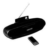
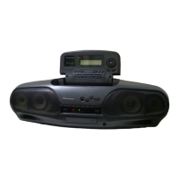
Panasonic RX-DT505 - CD Section Measurements and Adjustments; Self Diagnostic Function

Panasonic RX-DT505
52 pages
To Next Page IconTo Next Page
To Previous Page IconTo Previous Page
Loading...
i,
RX-DT505
RX-DT505
|
@
ALIGNMENT
POINT
<CD
SECTION>
Caution:
ah
we
Moat,
18
ePlease
refer
to
Circuit
Board
and
Wiring
Connection
Diagram
for
test
point
locations.
@\t
is
very
dangerous
to
look
at
or
touch
the
laser
beam.
(Laser
radiation
is
invisible.)
With
the
unit
turned
“on”,
laser
radiation
is
emitted
from
the
pickup
lens.
BEST
EYE
Mechanical
adjustment
screw
Avoid
exposure
to
the
laser
beam,
especially
when
performing
adjustments.
]
Measuring
Instruments
and
Special
Tools
eTest
disc
@Allen
wrench
(M2.0)
(SZZP1101C)
1.
Playability
test
disc
(SZZP1054C)
Oscilloscope
2.
Uneven
test
disc
(SZZP1056C)
y
[
Solder
the
lead
wire
intothe
soldered
=|
Mechanical
Lo
adjustment
hole
(1)
MECHANICAL
ADJUSTMENT
eWhen
the
traverse
deck
is
replaced,
making
adjustments
is
not
necessary.
(The
traverse
deck
ass’y
is
already
ad-
justed.)
Make
adjustments
to
improve
playability
when
the
traverse
deck
has
not
been
replaced.
Make
the
electrical
adjust-
ments
first.
1.
Connect
the
oscilloscope's
CH.
1
probe
across
KATA
MAAARASA
SO?
Fig.
5
+)
an
i
onthe
Seno
PCE.
LAA
AAAAAA
KAA
YANN
ISS0.0.0,08.00.75
a
ee
on
carers
\\
AVA
|
Input
coupling
................e
ccc
ee
eee
AC
\|
\A\VAY
AAA
|_|
SELF
DIAGNOSTIC
FUNCTION
7
peat
al
ea
crepes
waging
Mie
\\V\
VV
VVVVYYV"
The
Self
Diagnostic
Function
is
equipped
with
RX-DT505.
Use
this
function
only
when
you
wish
to
check
the
3.
Leave
the
player
in
Play
mode
and
place
it
as
shown
XY
NYY
VYVVY
VY
rY\
!
following
items.
in
the
figure
on
the
right.
CX
XOOOODOX
(It
is
necessary
to
use
the
remote
controller
supplied
with
RX-DT505
for
the
self
diagnostic
function.)
4.
Alternately
adjust
the
two
mechanical
adjusting
L
eee
ee
Check
of
all
indicati
eCneck
of
all
Indications
on
When
you
adjust
the
mechanical
adjustment,
play
track
19
on
the
test
disc
(SZZP1056C).
CD
P.C.B.
Extension
cable
(RFKZ0009)
Allen
wrench
2-pin
connector
(SZZP1101C)
(2mm)
Fig.
6
screws
with
the
2.0
mm
allen
wrench
(SZZP1101C)
pene
Use
the
di
tic
functi
n
LCD
is
not
displayed
I
until
the
RF
signal
amplitude
variation
on
the
oscillo-
Minimize
the
variation
of
amplitude.
eCheck
of
LCD
short-circuit
Beas
eee
gern
Be
ee
a
aaa
scope
is
minimized.
(Shown
in
Fig.
6)
5.
After
completing
the
adjustment,
lock
the
mechanical
[How
to
set
the
self
diagnostic
function]
adjustments
with
lock
paint
(RZZOLO1).
Follow
the
procedures
outlined
below
to
set
the
self
diagnostic
function
mode
before
the
self
diagnostic
function.
1.
Connect
the
AC
power
cord
of
the
RX-DT505
to
an
AC
outlet
and
turniton.
(2)
BEST
EYE
(PD
BALANCE)
ADJUSTMENT
2.
Press
the
4”
button
and
afterward
“7”
button
the
remote
|
1.
Connect
the
oscilloscope’s
CH.1
probe
across
udey4
(+)and
pisygek}
(V-REF)
on
the
Servo
‘4
PA
NAIMAMAA
AAA
AAA
AOS?
&
\
VARAAAAAARAA
A\\\\
conntrolier
while
keeping
the
TAPE/U
button
pressed.
oe
The
indication
in
Fig.
1
will
be
displayed.
b
(
!
a
fe
Gachloscons
setting:
AMMAMAARAA
|
oo
ONE
airs
Sener
eee
200
mV
\\
VWVYVWV\\
\\i
SWEEP
j.cue waittnesnieiss
macau
osc
0.5
usec
\
h
)
/\
4
Fig.
1
Input
coupling
.........
0.0
cece
eee
eee
eee
AC
AVY
VVYVV
\/
\/
\/
\/
\/
\\
2.
Switch
the
player
power
ON,
and
play
the
1
kHz
(track
/\
XY
i
f\
('\
[NY
\
)
1)
on
test
disc
(SZZP1054C).
VVVNVVVUVY
VV
VV
3.
Adjust
VR701
until
the
RF
signal
eye
pattern
ampli-
||
(DOOR,
on
ALL
INDICATIONS
ON
THE
LCD
;
tude
is
maximized.
LY
Pee
Pe
et
LS
ress
the
“8”
button
on
the
remote
controller.
All
indications
will
——-
aa
appear
for
about
1
second
on
the
LCD.
(Refer
to
Fig.
2)
ON
CSWEE
TIMER-REC_OFF
(SEE)
SLEEP
VOLUME
If
an
indication
is
not
displayed,
the
LCD
or
the
LCD
drive
system
is
|
i
ai
ae
Wd
ier
lic
Abe
:
I=}
Maximize
the
amplitude
defective.
DTDBCOOMNOODHEES
CD
ms
|
PROGRAM
)
(RANDOM
(mono
}
Ctiwk)
Tepit>
Cates”
(3)
CHECK
OF
PLAY
OPERATION
AFTER
ADJUSTMENT
Fig.
2
‘Checking
Skip
Search
“Checking
Playability
1.
Play
an
ordinary
musical
program
disc.
1.
Play
the
0.7
mm
black
dot
and
the
0.7
mm
wedge
on
2.
Press
the
skip
button
to
check
for
normal
skip
search
the
test
disc
(SZZP1054C)
and
verify
that
no
sound
CHECK
OF
LCD
SHORT-CIRCUIT
operation
(in
both
the
forward
and
reverse
direc-
skip
or
noise
occurs.
@Press
the
“9”
button
on
the
remote
controller.
The
indications
will
PES
ti
2
Pl
is
iddi
.
appear
as
shown
in
Fig.
3.
I
id
|
a
=
I
ions).
-
Play
the
middie
tracks
of
the
phe!
test
disc
and
If
another
indication
appears,
the
LCD
is
defective.
ae
Ese
NR
alah
SP
rt
‘Checking
Manual
Search
verify
that
no
sound
skip
or
noise
occurs.
C
1.
Play
an
ordinary
musical
program
disc.
2.
Press
the
manual
search
button
to
check
for
smooth
Fig.
3
manual
search
operations
at
either
low
or
high
speed
|
{in
both
the
forward
and
reverse
directions).
-51-—
-52-

Related product manuals