1. 6-2
2.
1. 7-2
2.
1. 8-2
2. 8-18
Outdoor Unit ...................................................................................................
Outdoor Unit Control PCB ...............................................................................
Capacity Ratio of Outdoor Unit ......................................................................
Cooling Capacity of Indoor Unit ....................................................................
1-1
1. 1-2
2. 1-5
2-1
1. 2-3
2. 2-17
3. 2-21
4. 2-28
4-2
3-1
4-1
1.
Contents
Line-up ............................................................................................................
Features of 3WAY VRF SYSTEM ....................................................................
Model Selection and Capacity Calculator .......................................................
System Design .............................................................................................
ELECTRICAL WIRING .................................................................................
SELECTING THE INSTALLATION SITE ......................................................
Outdoor Unit ..................................................................................................
Section 1: OUTLINE OF 3WAY VRF SYSTEM ......................................................................
Section 2: DESIGN OF 3WAY VRF SYSTEM ........................................................................
Section 3: Control of 3WAY VRF SYSTEM ...........................................................................
Section 4: 3WAY VRF SYSTEM UNIT SPECIFICATIONS .....................................................
6. 2-39HOW TO PROCESS TUBING ......................................................................
5. 2-34HOW TO INSTALL THE OUTDOOR UNIT ...................................................
7. 2-42AIR PURGING ..............................................................................................
8. 2-45Optional Parts ...............................................................................................
v
1. Main Operating Functions
2. Simplified Remote Controller
3. System Controller
4. Schedule Timer
5. Intelligent Controller (CZ-256ESMC1U)
6. Communication Adaptor (CZ-CFUNC1U)
7. Remote Sensor
8. LonWorks Interface (CZ-CLNC1U)
* Refer to the 2WAY VRF SYSTEM TECHNICAL DATA (TD831179)
* Refer to the VRF SYSTEMS INDOOR UNIT TECHNICAL DATA (TD831178)
1. High-spec Wired Remote Controller (CZ-RTC3)
4. ECONAVI Sensor (CZ-CENSC1)
5. Wireless Remote Controller
6. Interface Adaptor (CZ-CAPC2U)
2. High-spec Wired Remote Controller (CZ-RTC5)
3. Timer Remote Controller (CZ-RTC4)
* Refer to the VRF SYSTEM TECHNICAL DATA (TD831178)
* Refer to the SERVICE MANUAL & TEST RUN SERVICE MANUAL (SM830246)
5. 4-Way Cassette 24” × 24” (Type Y2)
2. Concealed Duct - Medium Static (Type F2)
13. Fresh Air Intake
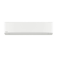
3. Wall Mounted (Type K2)
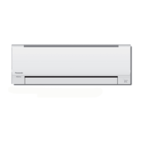
4. Wall Mounted (Type K1)
6. Concealed Duct - Low Static (Type M2)
9. 1-Way Cassette (Type D1)
7. 4-Way Cassette 36” × 36” (Type U2)
8. Ceiling (Type T2)
10. Concealed Duct - High Static (Type E1)
11. Floor Standing (Type P1)
12. Concealed Floor Standing (Type R1)
5-1Section 5: TEST RUN .............................................................................................................

 Loading...


