2-16
Design of VRF SYSTEM
3. How to install the indoor unit
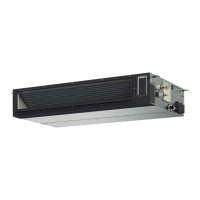
3-1-3. Placing the Unit Inside the Ceiling
This unit is equipped with the drain pump. Check a tape measure or carpenter’s level.
Before installing the ceiling panel, complete the work of drain pipe and refrigerant pipe installation.
(1)
pitch of the suspension bolts using the supplied full-scale
installation diagram. (Fig. 2-21)
Tubing and wiring must be laid inside the ceiling when
suspending the unit. If the ceiling is already constructed,
lay the tubing and wiring into position for connection to
the unit before placing the unit inside the ceiling.
(2)
distance between the bottom of the bolt and the bottom
of the unit of more than 18 mm as shown in Fig. 2-21.
(3)
supply) onto each of the 4 suspension bolts as shown in
Fig. 2-22. Use 1 nut and 1 washer for the upper side, and
2 nuts and 1 washer for the lower side, so that the unit
will not fall off the suspension lugs.
(4)
ceiling bottom is 12 to 17 mm. Tighten the nuts on the
upper side and lower side of the suspension lug.
(5)
fan parts during transport.
(6)
When placing the unit inside the ceiling, determine the
The length of suspension bolts must be appropriate for a
Thread the 3 hexagonal nuts and 2 washers (field
Adjust so that the distance between the unit and the
Remove the protective polyethylene used to protect the
Check with a tape measure or carpenter’s level.
Fig. 2-22
Nuts and washers
(use for upper and lower)
Double nut
12 – 17 (mm)
Notch
Suspension lug
Suspension bolt
3-1-4. How to Process Tubing
Refer to the TECHNICAL DATA “TD831159”.
Fig. 2-21
Over 18 mm
12 – 17 mm
Air
conditioner
Ceiling
Screw for
attaching paper
(4 points)
Paper model for
installation
Open the ceiling
as large as this
paper outline
Air
conditioner
Over 18 mm
Paper model
for installation
Full-scale installation diagram
(printed on top of container box)
Ceiling
TDxxxxxx-002WAYVRF.indb16TDxxxxxx-002WAYVRF.indb16 2014/01/3017:52:302014/01/3017:52:30

 Loading...