2-49
Design of VRF SYSTEM
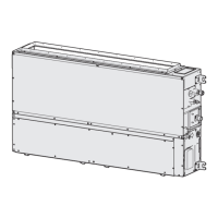
3. How to install the indoor unit
To unmount indoor unit
(1)
(2)
(3)
Remove the screw cover on the bottom surface.
(Fig. 2-139)
Fasten the frame to the rear panel using the 2 supplied
tapping screws 4 x 10 mm. (Fig. 2-139)
Press the 2
marks on the lower part of the indoor unit
and unlatch the tabs. Then lift the indoor unit and unmount.
(Fig. 2-138)
NOTE
Under normal conditions, the installation design calls for a less
than 2 mm gap between the air conditioner unit and the wall.
Confirm that the gap is appropriate (less than 2 mm).
3-6-8. Drain Hose
a)
b)
c)
The drain hose should be slanted downward to the
outdoors. (Fig. 2-140)
Never form a trap in the course of the hose.
If the drain hose will run in the room, insulate the hose with
insulation* so that chilled condensation will not damage
furniture or floors. (Fig. 2-141)
*Foamed polyethylene or its equivalent is recommended.
WARNING
Do not supply power to the
unit or operate it until all
tubing and wiring to the
outside unit are completed.
Risk of Electric Shock
Fig. 2-138
Push
Screw
cover
Fig. 2-139
Fig. 2-140
Fig. 2-141
Screw
Slant
Drain
hose
Indoor
unit
Condensation
Insulation material
(Locally purchased)
must be used.
TDxxxxxx-002WAYVRF.indb49TDxxxxxx-002WAYVRF.indb49 2014/01/3017:52:322014/01/3017:52:32

 Loading...