Do you have a question about the Panasonic SA-AK17 and is the answer not in the manual?
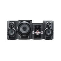
| Type | Mini Hi-Fi System |
|---|---|
| Speaker Configuration | 2 speakers |
| Number of Channels | 2 |
| CD Player | Yes |
| CD Changer | No |
| Number of Discs | 1 |
| Radio Tuner | Yes |
| Tuner Bands | FM/AM |
| Input Sensitivity | 500 mV |
| Speaker Type | 2-way |
| Playback Media | CD, CD-R/RW |
| Connectivity | AUX input |
Technical details for amplifier, tuner, and CD sections.
Technical details for cassette deck and overall unit specifications.
Critical safety warnings, handling precautions, and grounding advice for technicians.
Explanation of the unit's protection circuitry and how it functions.
Step-by-step guide for safely replacing the fuse in the AC mains plug.
Instructions for connecting FM, AM antennas, and front speakers.
Steps for connecting the AC power cord to the unit and power outlet.
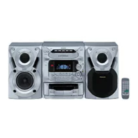
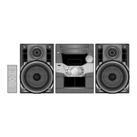
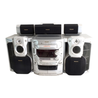
Identification of controls on the Main Unit (A, C) and Center Console (B).
Detailed steps for recording audio broadcasts from the radio.
Detailed steps for recording audio from CDs.
Explanation of the CD Manager feature for selecting tracks/CDs for recording.
Instructions for copying audio from one cassette tape to another.
Essential safety precautions and handling guidelines for service personnel.
Detailed steps for checking the operation of various PCBs.
Step-by-step guides for replacing major components like traverse deck and power amplifier.
Procedures for disassembling and reassembling unit sub-assemblies like traverse and disc tray.
Steps to access the unit's self-diagnostic mode for troubleshooting.
Procedures for performing cassette and CD mechanism diagnostic tests.
How to clear error codes and exit the self-diagnostic function.
List and explanation of error codes related to the cassette mechanism.
List and explanation of error codes for the CD and changer mechanisms.
List and explanation of error codes related to power supply issues.
Steps to activate the CD test mode for diagnostics.
Interpretation of automatic alignment results and error codes.
Specifies conditions and tools required for measurements and adjustments.
Procedures for adjusting head azimuth and tape speed for optimal playback.
Steps for checking bias and erase voltage levels.
Alignment procedures for the AM Intermediate Frequency (IF) and Radio Frequency (RF) stages.
Identifies specific alignment points for the cassette deck section.
Visual identification of integrated circuits, transistors, and diodes used in the unit.
Detailed pinout and function description for IC701 and IC703.
Detailed pinout and function description for the IC702 servo processor.
Circuit diagrams for servo, panel interface, and mechanism systems.
Circuit diagrams for motor control and detection switches.
Schematics for transformer, motor control, and CD detection circuits.
Schematic for the spindle position detection circuit.
Layout diagrams for the transformer and sub-transformer PCBs.
Layout diagram for the servo control PCB.
Layout diagrams for main, tuner, and panel interface PCBs.
Layout diagrams for cassette mechanism and CD deck PCBs.
Layout diagram for the power supply PCB.
System block diagram for optical pickup and servo control.
Block diagrams for signal processing, microprocessor interface, and control logic.
Block diagrams for mechanism control and power supply systems.
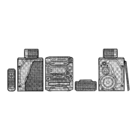
Exploded views showing part locations for both Deck 1 and Deck 2 mechanisms.
List of part numbers and names for cassette deck and loading mechanisms.
List of part numbers for ICs, transistors, diodes, and other major components.
List of part numbers for resistors, capacitors, switches, and connectors.