(2) CD-R/RW (CD-DA, MP3, WMA formatted disc)
(3) MP3/WMA
Bit rate
MP3, WMA 32 kbps to 320 kbps
Sampling frequency
MP3, WMA 32 kHz, 44.1 kHz, 48 kHz
CD-DA 44.1 kHz
Decoding 16 bit linear
Digital filter 8fs
D/A converter MASH (1 bit DAC)
Pick up
Wavelength 780 nm
Beam Source Semiconductor laser
udio output (Disc)
Number of channels 2 (Stereo) (FL,FR)
n GENERAL
Power supply AC 120 V, 60Hz
1 Safety Precautions
4
1.1. General Guidelines
4
1.2. Caution for fuse replacement
5
1.3. Before repair and adjustment
5
1.4. Protection Circuitry
5
2 Prevention of Electro Static Discharge (ESD) to
Electrostatically Sensitive (ES) Devices
5
3 Handling Precautions For Traverse Deck
7
4 Precaution of laser diode
8
5 Handling the Lead-free Solder
9
5.1. About lead free solder (PbF)
9
6 New Features
10
6.1. CRS1 Mechanism Overview
10
6.2. Music Port
12
7 Accessories
13
8 Operating Instructions Procedures
14
9 Self diagnosis and special mode setting
16
9.1. Special Mode Table
16
9.2. Error code Table
18
10 Assembling and Disassembling
22
10.1. Caution
22
10.2. Disassembly flow chart
23
10.3. Main Parts Location
24
10.4. Disassembly of Top Cabinet
25
10.5. Disassembly of Rear Panel
25
10.6. Disassembly of CD Changer Unit (CRS1)
25
10.7. Disassembly of Main P.C.B.
27
Power consumption 100 W
Power consumption in standby
mode
0.28 W
Dimensions (W x H x D) 250 x 330 x 343 mm
(9-27/32” x 13” x 13-1/2”)
Mass 6.6 kg (14.6 lb.)
Operating temperature range +5to+35°C(+41to+95°F)
Operating humidity range 5 to 90% RH (no condensation)
n SYSTEM
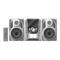
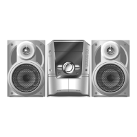
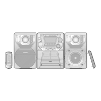
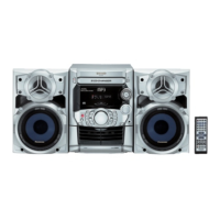
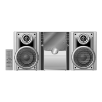
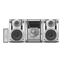
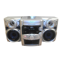
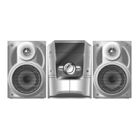
SC-AK240 (P) Music center: SA-AK240 (P)
Speaker: SB-AK240 (P)
SC-AK240 (PC) Music center: SA-AK240 (PC)
Speaker: SB-AK240 (P)
Notes:
1. Specifications are subject to change without notice. Mass and
dimensions are approximate.
2. Total harmonic distortion is measured by the digital spectrum
analyzer.
10.8. Disassembly of Transformer P.C.B.
27
10.9. Disassembly of Power P.C.B.
28
10.10. Disassemb ly of Front Panel Unit
29
10.11. Disassemb ly for Panel P.C.B.
30
10.12. Disassemb ly of Deck mechanism unit
31
10.13. Disassemb ly of Deck P.C.B.
31
10.14. Disassemb ly of Traverse Unit
31
10.15. Disassemb ly of optical pickup unit (CD mechanism )
33
10.16. Disassemb ly of Deck Mechanism
35
10.17. Replaceme nt for cassette lid
38
10.18. Rectificatio n for tape jam problem
38
11 Service Fixture and Tools
40
12 Service Positions
40
12.1. Checking and Repairing of Main P.C.B.
40
12.2. Checking and Repairing of Transformer P.C.B.
41
12.3. Checking and Repairing of Panel, Deck & Deck
Mechanism P.C.B.
42
12.4. Checking and Repairing of Power P.C.B.
43
13 Measurements and Adjustments
44
13.1. Cassette Deck Section
44
13.2. Tuner Section
45
14 Voltage and Waveform Chart
47
14.1. CD Servo P.C.B. & Main P.C.B.
47
14.2. Power P.C.B. and Transformer P.C.B.
49
14.3. Waveform Chart
50
15 Wiring Connection Diagram
52
16 Block Diagram
53
CONTENTS
Page Page
2
SA-AK240P / SA-AK240PC




 To Next Page