udio output (Disc)
Number of channels 2 (Stereo) (FL,FR)
n GENERAL
1 Safety Precautions 4
1.1. General Guidelines
4
1.2. Before repair and adjustment
4
1.3. Protection Circuitry
4
2 Prevention of Electro Static Discharge (ESD) to
Electrostatically Sensitive (ES) Devices
5
3 Handling Precautions For Traverse Deck
6
4 Precaution of laser diode
7
5 Handling the Lead-free Solder
8
5.1. About lead free solder (PbF)
8
6 New Features
9
6.1. CRS1 Mechanism Overview
9
6.2. Music Port
11
7 Accessories
12
8 Operating Instructions Procedures
13
9 Self diagnosis and special mode setting
15
9.1. Special Mode Table
15
9.2. Error code Table
17
10 Assembling and Disassembling
21
10.1. Caution
21
10.2. Disassembly flow chart
22
10.3. Main Parts Location
23
10.4. Disassembly of Top Cabinet
24
10.5. Disassembly of Rear Panel
24
10.6. Disassembly of CD Changer Unit (CRS1)
24
10.7. Disassembly of Main P.C.B.
26
10.8. Disassembly of Transformer P.C.B.
26
10.9. Disassembly of Power P.C.B.
27
Power supply AC 120 V, 60Hz
Power consumption 100 W
Power consumption in standby
mode
0.28 W
Dimensions (W x H x D) 250 x 330 x 343 mm
Mass 6.6 kg
Operating temperature range +5 to +35°C
Operating humidity range 5 to 90% RH (no condensation)
n SYSTEM
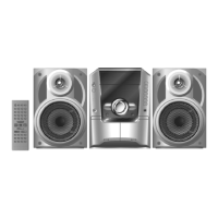
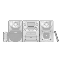
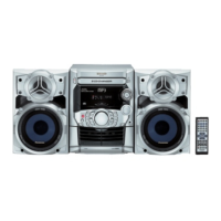
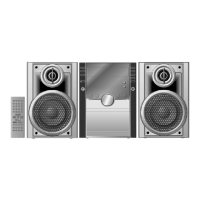
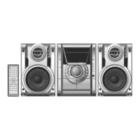
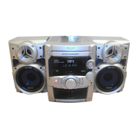
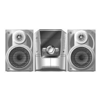
SC-AK240 (PL) Music center: SA-AK240 (PL)
Speaker: SB-AK240 (GC)
For information on speaker system, please refer to the original
Service Manual (Order No. MD0512446A3)
Notes:
1. Specifications are subject to change without notice. Mass and
dimensions are approximate.
2. Total harmonic distortion is measured by the digital spectrum
analyzer.
10.10. Disassemb ly of Front Panel Unit
28
10.11. Disassemb ly for Panel P.C.B.
29
10.12. Disassemb ly of Deck mechanism unit
30
10.13. Disassemb ly of Deck P.C.B.
30
10.14. Disassemb ly of Traverse Unit
30
10.15. Disassemb ly of optical pickup unit (CD mechanism )
32
10.16. Disassemb ly of Deck Mechanism
34
10.17. Replaceme nt for cassette lid
37
10.18. Rectificatio n for tape jam problem
37
11 Service Fixture and Tools
39
12 Service Positions
39
12.1. Checking and Repairing of Main P.C.B.
39
12.2. Checking and Repairing of Transformer P.C.B.
40
12.3. Checking and Repairing of Panel, Deck & Deck
Mechanism P.C.B.
41
12.4. Checking and Repairing of Power P.C.B.
42
13 Adjustment Procedures
43
13.1. Cassette Deck Section
43
13.2. Tuner Section
44
14 Voltage and Waveform Chart
46
14.1. CD Servo P.C.B. & Main P.C.B.
46
14.2. Power P.C.B. & Transformer P.C.B.
48
14.3. Waveform Chart
49
15 Wiring Connection Diagram
51
16 Block Diagram
53
17 Schematic Diagram
57
17.1. Notes of Schematic Diagrams
57
17.2. (A) CD Servo Circuit
59
CONTENTS
Page Page
2
SA-AK240PL